Do you have a question about the JUMO dTRANS T02 PCP and is the answer not in the manual?
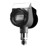
This document provides essential information for the operation and setup of the JUMO dTRANS T02 PCP.
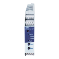
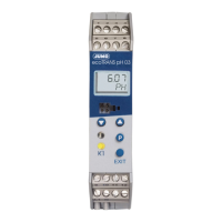
Details the user interface levels and the function of the 'Span' and 'Zero' buttons.
Explains the meaning of LED blink patterns for operational status feedback.
Illustrates how to connect a relay to the device's open-collector output.
Contact information for the main JUMO entity in Fulda, Germany.
Defines the product's basic version and coding system for configuration.
Details programmable input types and output signal configurations.
Lists available supply voltage ranges for the device.
Information on included standard accessories and other available optional items.
Provides a visual schematic for all device connections.
Details how to connect the power supply and various terminals.
Illustrates wiring for Thermocouple and Resistance Thermometer inputs.
Wiring configurations for various input signal types.
Wiring for voltage, current, and open-collector outputs.
Important note regarding the isolation of output negative poles.
Alerts users to potential isolation issues with the setup interface.
Covers cable choice, qualified personnel, and power isolation requirements.
Advises on avoiding interference and managing inductive loads.
Instructions for laying out and grounding shielded cables.
Warnings about connecting loads and operating in hazardous areas.
Highlights the risk of device destruction due to incorrect electrical connections.
Explains potential equalizing currents and damage risks with PC interface connection.
Outlines necessary safety steps when output circuits are not isolated.
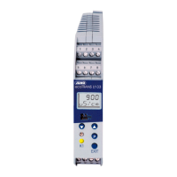
Identifies LEDs for status and push-buttons for parameter level operation.
Describes device status and LED signals during normal operation.
Details device status and LED signals when in programming mode.
Explains how to distinguish between operating and parameter levels.
Defines the two primary operational states: Operating and Parameter Level.
Describes how to enter and leave the programming mode.
How to adjust parameter values using the 'Span' and 'Zero' buttons.
Procedure for confirming altered parameter values.
Method for checking output values during programming.
How to set upper and lower limit values using buttons and PC program.
Describes available functions for limit monitoring via PC setup.
Enabling and understanding the fault output signal.
Enabling and configuring the frequency output signal.
Using buttons to adjust the zero point and slope of the output signal.
Formula for calculating the new converted value during calibration.
How to use the Teach-in function to set the zero point (0% value).
A step-by-step example of using the Teach-in function.
Tips on correctly confirming values and avoiding unintended alterations.
Advice on managing accidental parameter modifications.
Note on advanced limit setting capabilities of the PC setup program.
Information on locked parameters and inhibition settings.
Details on output availability and accuracy for activated/default settings.
How the setup plug affects the frequency output operation.
Comprehensive list of parameters adjustable via the PC setup program.
Advantages of using the PC setup program for configuration and management.
Example of interfacing the device with a PLC digital input.
Demonstrates calculation for determining the correct resistance (RA).
Illustrates wiring a relay to the device's open-collector output.
Contact details for the JUMO UK branch.
Contact details for the JUMO USA branch.
| Brand | JUMO |
|---|---|
| Model | dTRANS T02 PCP |
| Category | Transmitter |
| Language | English |