S
Stacy GarciaAug 9, 2025
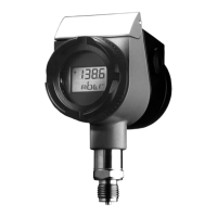
Why JUMO Transmitter has no output signal?
- BBrandy CurryAug 9, 2025
The JUMO Transmitter might not be sending an output signal due to several reasons. It could be due to no supply voltage, so check the supply voltage. There might be a cable break or incorrect connection, so check the connecting cables. Another reason could be no input pressure, in that case check the connection to the pressure medium. Finally, there may be a fault in the pressure transmitter, caused by impermissible operating conditions, in this case return the pressure transmitter to the supplier, with a detailed description of the fault.