Do you have a question about the JUMO dTRANS T03 Series and is the answer not in the manual?
General safety guidelines and warning symbols for user protection.
Details on the transmitter's purpose, output signals, and performance characteristics.
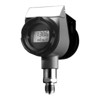
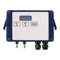
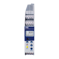
Comparison of dTRANS T03 models based on input, mounting, and output specifications.
Information found on the device's nameplate, including type, part, and serial numbers.
Explanation of the device's order code components and available options.
Lists standard and optional accessories like setup programs, interfaces, and mounting brackets.
Wiring diagram and terminal connections for the dTRANS T03 J model.
Wiring diagram and terminal connections for the dTRANS T03 B model.
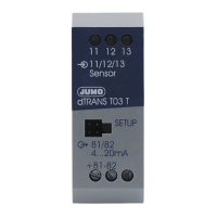
Wiring diagram and terminal connections for the dTRANS T03 T model.
Wiring diagram and terminal connections for the dTRANS T03 BU model.
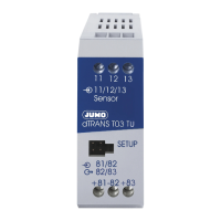
Wiring diagram and terminal connections for the dTRANS T03 TU model.
Physical dimensions and mounting options for various dTRANS T03 models.
Illustrates wiring for current output with supply units and isolators.
Illustrates wiring for voltage output with a supply unit.
Specifies PC requirements and lists adjustable/configurable parameters for the transmitter.
Diagrams for connecting the transmitter for calibration and configuration procedures.
How to start the setup program, including online and offline operation modes.
Overview of the setup program's menu bar, toolbar, and working area for navigation.
Details on Setup data, Device Assistant, Input editing, and TAG number assignment.
Procedures for transferring data to/from the device, fine calibration, and range calibration.
Steps for defining and setting the measurement range span.
| Product Series | dTRANS T03 |
|---|---|
| Category | Transmitter |
| Measurement Type | Temperature |
| Protection Class | IP65 |
| Input | RTD, Thermocouple |
| Output | Relay |
| Accuracy | ±0.1 % of measuring span |
| Operating Temperature Range | -40 to +85 °C |
| Housing Material | Aluminum |
| Sensor Connection | Screw terminals |
| Electrical Connection | Cable gland |
| Communication | PROFIBUS PA, FOUNDATION Fieldbus |
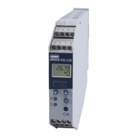
| Display | Optional LCD |
| Configuration | Via PC |