5 Technical data
26
Resistance transmitter and resistor/potentiometer
Voltage, current (standard signals)
Measuring circuit monitoring
The device response in the event of a fault is configurable.
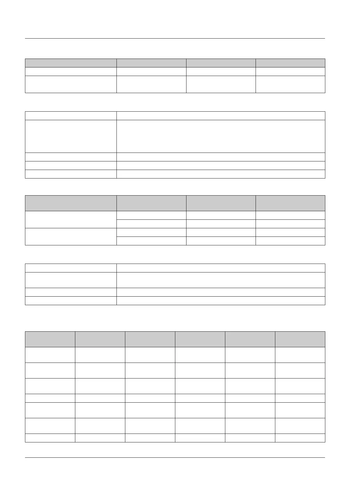
Designation Measuring range Accuracy
a
Measuring current
Resistance transmitter 0 to 4000 Ω≤0.1 % 50 μA
Resistance/potentiometer 0 to 400 Ω≤0.1 % 500 μA
0to4000Ω≤0.1 % 50 μA
a
The accuracy value refers to the maximum measuring range. Small measuring spans lead to reduced linearization
accuracy.
Ambient temperature influence ≤ 100 ppm/K
Connection type
Resistance transmitter 3-wire circuit
Resistance/potentiometer 2-wire/3-wire circuit
Sensor line resistance max. 30 Ω per line
Sampling rate 150 ms
Input filter Digital filter, 2nd order; filter constant can be set from 0 to 100.0 s
Designation Measuring range Accuracy
a
Input resistance or bur-
den voltage
Voltage 0 to 10 V ≤ 0.1 % > 500 kΩ
2to10V ≤ 0.1 % > 500 kΩ
Current 4to20mA ≤ 0.1 % < 2.5 V
0to20mA ≤ 0.1 % < 2.5 V
a
The accuracy value refers to the maximum measuring range. Small measuring spans lead to reduced linearization
accuracy.
Ambient temperature influence ≤ 100 ppm/K
Deviation below/above the mea-
suring range
According to NAMUR recommendation NE 43 (only current input 4 to 20mA)
Sampling rate 150 ms
Input filter Digital filter, 2nd order; filter constant can be set from 0 to 100.0 s
Measuring
probe
Measuring
range underflow
Measuring
range overflow
Short-circuit
(probe/line)
Break (probe/
line)
Polarity
RTD temperature
probe
++ ++ ++ ++ ---
Resistance/po-
tentiometer
--- ++ --- ++ ---
Resistance trans-
mitter
--- --- (+)
a
(+)
b
---
Thermocouple ++ ++ --- ++ (+)
c
Current
0to20mA
--- ++ --- --- ---
Current
4to20mA
++ ++ ++ ++ ++
Voltage 0to10V --- ++ --- --- ++
 Loading...