19
3 Electrical connection
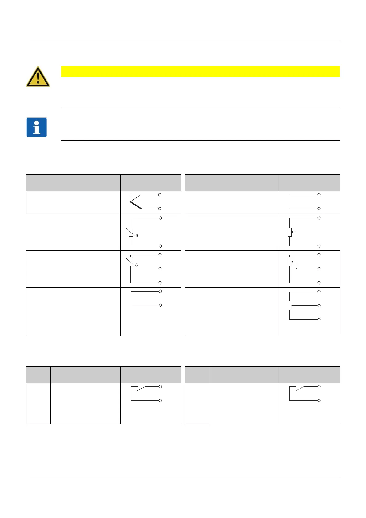
3.3 Connection diagram
CAUTION!
In unfavorable conditions, the temperature may exceed 60 °C at the terminals.
As a result, the insulation of the cables connected at the terminals may be damaged.
The affected cables must be heat-resistant up to at least 80 °C.
NOTE!
There is an individual connection diagram on the housing that corresponds to the ordered device ver-
sion.
3.3.1 Analog input
The analog input version is identical for all types.
3.3.2 Digital inputs
The digital input version is identical for all types.
Measuring probe/
standard signal
Symbol and termi-
nal designation
Measuring probe/
standard signal
Symbol and termi-
nal designation
Thermocouple 6 Current DC 0(4) ... 20 mA 6
77
RTD temperature probe
two-wire circuit
5 Resistance/potentiometer
two-wire circuit
5
77
RTD temperature probe
three-wire circuit
5 Resistance/potentiometer
three-wire circuit
5
66
77
Voltage DC 0(2) ... 10 V
(useable as alternative to digital
input 2)
8 Resistance transmitter
A = Start
E = End
S = Slider
5
76
7
Input Version Symbol and termi-
nal designation
Input Version Symbol and termi-
nal designation
1 Digital input for poten-
tial-free contact
(useable as alternative
to digital output 3)
9 2 Digital input for poten-
tial-free contact
(only usable if the ana-
log input is not config-
ured as DC 0(2) ... 10 V)
8
10 10
 Loading...