5. Set the three DIP switches on the power supply to indicate whether one or both power feeds are used, and to indicate
the amperage of the feeds. Together, these switches determine if the chassis operates at 3,000 W, 5,000 W, or 5,500 W.
Set both switch 1 and switch 2 to the on (|) position when using both power source inputs; power is shared. When you
are not using source redundancy, set the unused source to the off (O) position. The LED turns red and indicates an
error if a source input is not in use and the DIP switch is on (|).
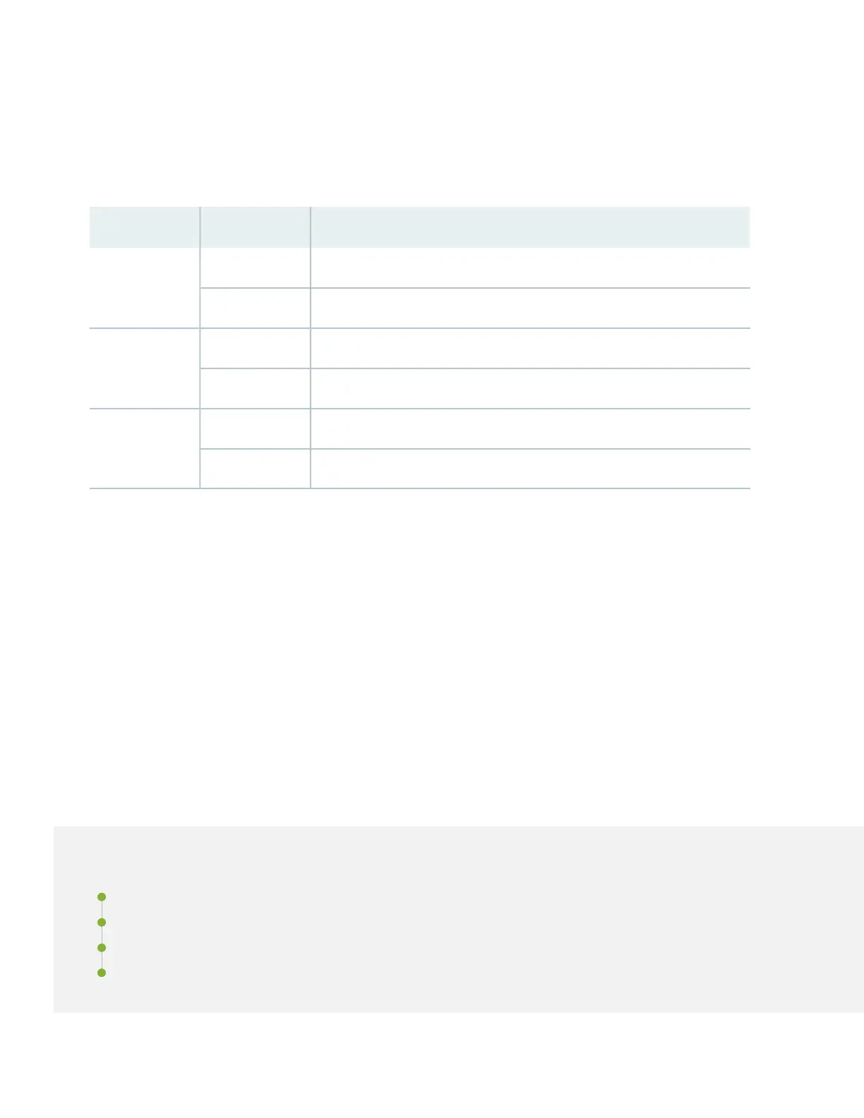
DescriptionStateSwitch
INP0 is present.On1
INP0 is not present.Off
INP1 is present.On2
INP1 is not present.Off
Enabled for 30-A feed; 5,000 W for single feed, 5,500 W for dual feeds.On3
Enabled for 20-A feed; power supply capacity is 3,000 W.Off
6. Plug in the AC power cord into the power outlet.
7. If the AC power source outlet has a power switch,set it to the on (|) position.
8. Set the power switch on the power supply to the on (|) position.
9. If you’re using two feeds, verify that the 1 and 2 LEDs on the power supply faceplates are steadily lit. These LEDs
correspond to INP0 and INP1.
Step 2: Up and Running
IN THIS SECTION
Connect to the Router | 8
Set a Root Password and an Optional Hostname | 9
Configure the Default Gateway and Ethernet Interface | 9
Configure Optional Routes, Services, and Commit the Configuration | 10
7