a. Secure the ring lug of the positive (+) DC power source cable from the first DC power source to a + terminal on the power
supply.
b. Secure the ring lug of the negative (–) DC power source cable from the first DC power source to the – terminal adjacent
to the + terminal on the DC power supply to which you connected the ring lug of the positive (+) DC power source cable
from the first DC power source.
c. Secure the ring lug of the positive (+) DC power source cable from the second DC power source to the other + terminal
on the power supply.
d. Secure the ring lug of the negative (–) DC power source cable from the second DC power source to the – terminal adjacent
to the + terminal on the DC power supply to which you connected the ring lug of the positive (+) DC power source cable
from the second DC power source.
e. Connect the ground wire to earth ground if the switch is not in a grounded rack.
f. Tighten the screws on the power supply terminals on both the power supplies until snug using the screwdriver. Do not
overtighten—apply between 8 lb-in. (0.9 Nm) and 9 lb-in. (1.02 Nm) of torque to the screws.
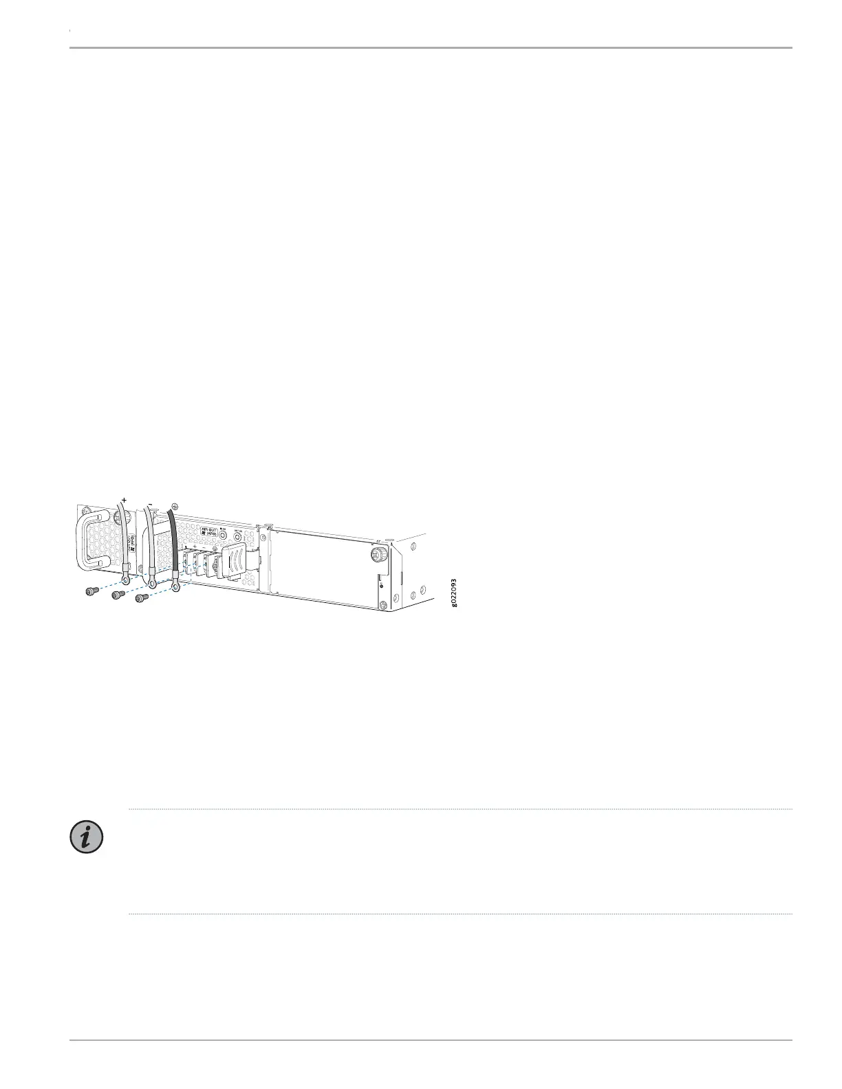
If you have a second installed power supply, connect it in the same way you did the first.
Figure 12: Connecting Power to an EX4300 Switch Powered by DC Power Supply
6. Replace the terminal block cover.
7. Close the input circuit breaker.
8. Verify that the IN OK and the OUT OK LEDs on the power supply are lit green and on steadily.
Part 5: Perform Initial Configuration
NOTE: To run the EZSetup script, the switch must have the factory-default configuration as the active configuration.
If you have configured any configuration on the switch and want to run EZSetup, see the documentation at https://
www.juniper.net/documentation/en_US/release-independent/junos/topics/task/configuration/
ex-series-switch-default-factory-configuration-reverting.html to revert to the factory-default configuration.
9Copyright © 2018, Juniper Networks, Inc.
EX4300 Switch Quick Start