Clearance Requirements
For the cooling system to function properly, the airflow around the chassis must be unrestricted. You must allow sufficient
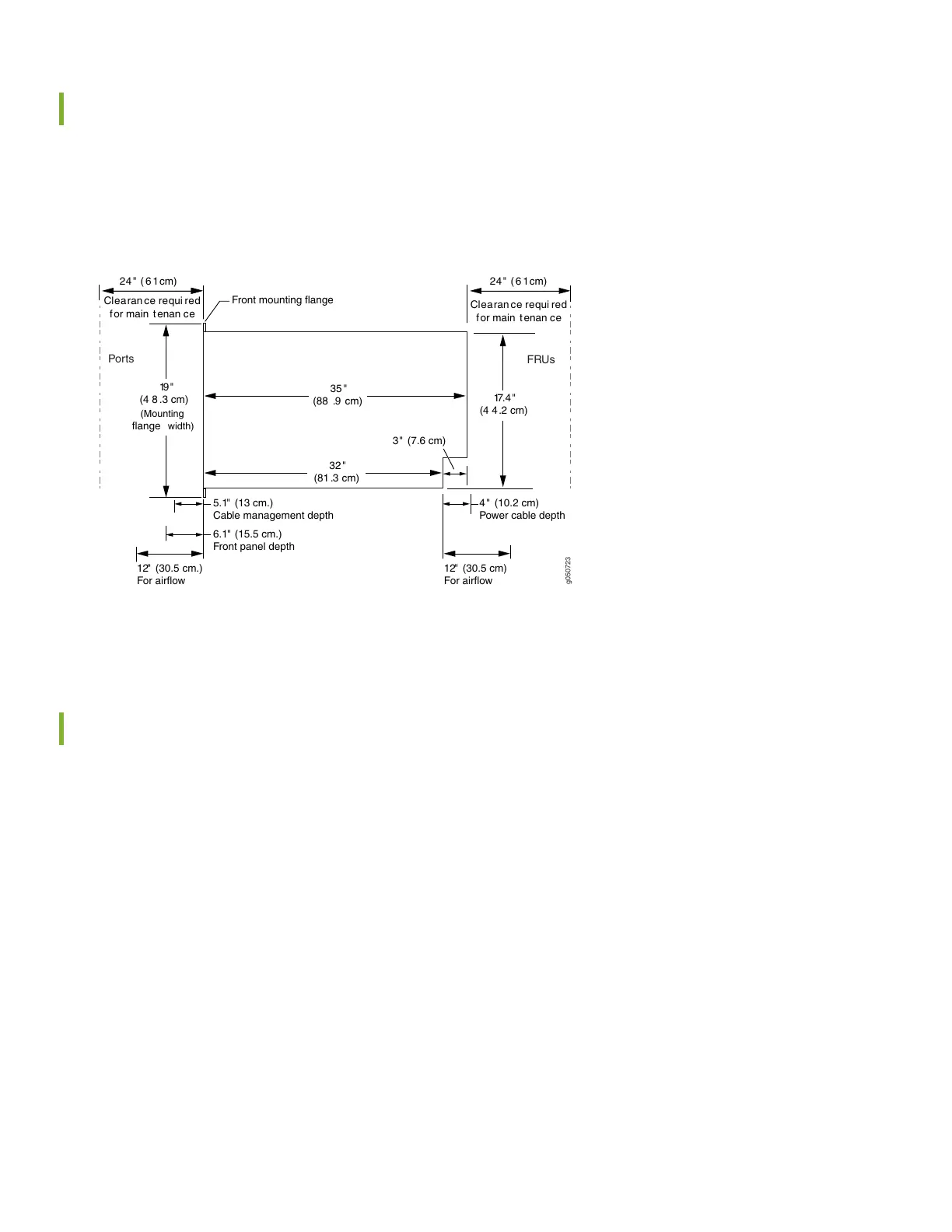
clearance around the installed chassis for cooling and maintenance (see Figure 1).
Figure 1: Clearance Requirements for Airflow and Hardware Maintenance for an MX10016
g050723
Clearan ce requi red
for main t enan ce
19"
(4 8 .3 cm)
32"
(81 .3 cm)
35 "
(88 .9 cm)
for main t enan ce
Clearan ce requi red
Front mounting flange
24 " ( 6 1cm) 24 " ( 6 1cm)
FRUs
Ports
17.4"
3" (7.6 cm)
4 " (10.2 cm)
Power cable depth
5.1" (13 cm.)
Cable management depth
6.1" (15.5 cm.)
Front panel depth
12" (30.5 cm)
For airflow
(4 4.2 cm)
(Mounting
flange width)
12" (30.5 cm.)
For airflow
If you are mounting an MX10016 in a rack with other equipment, ensure that the exhaust from other equipment does
not blow into the intake vents of the chassis.
Cooling and Airflow Requirements
The cooling system in an MX10016 chassis consists of dual fan trays and dual fan tray controllers. There is no air filter in
an MX10016.
The air intake to cool the chassis is located on the port (line card) side of the chassis. Air flows into the chassis from the
ports in the control boards and line cards, through the Switch Fabric Boards (SFBs), and exits from the fan trays and the
power supplies. This airflow is called port-to-FRU cooling or airflow out (AFO). See Figure 2.
3