How to Set Up Your SRX340 Services Gateway
4
3. Turn on the power to the AC power receptacle.
4. Note the following LED indications. Wait until the STATUS LED is solid green
before proceeding to the next step.
970
LED State
ALARM • Solid amber (noncritical alarm).
• Solid red (critical alarm).
• O (no alarms).
STAT • Solid green (operating normally).
• Solid red (error detected).
PWR • Solid green (receiving power).
• Solid red (power failure).
• O (no power).
HA • Solid green (all HA links are available).
• Solid amber (some HA links are unavailable).
• Solid red (HA links are not functional).
• O (HA is disabled).
mPIM0 , mPIM1, mPIM2,
and mPIM3
• Solid green (Mini-PIM is functioning normally).
• Solid red (Mini-PIM hardware failure).
• O (Mini-PIM is not present or Mini-PIM is not detected
by the device).
Configure the Device Using J-Web
To configure the device using J-Web, follow the steps in this section.
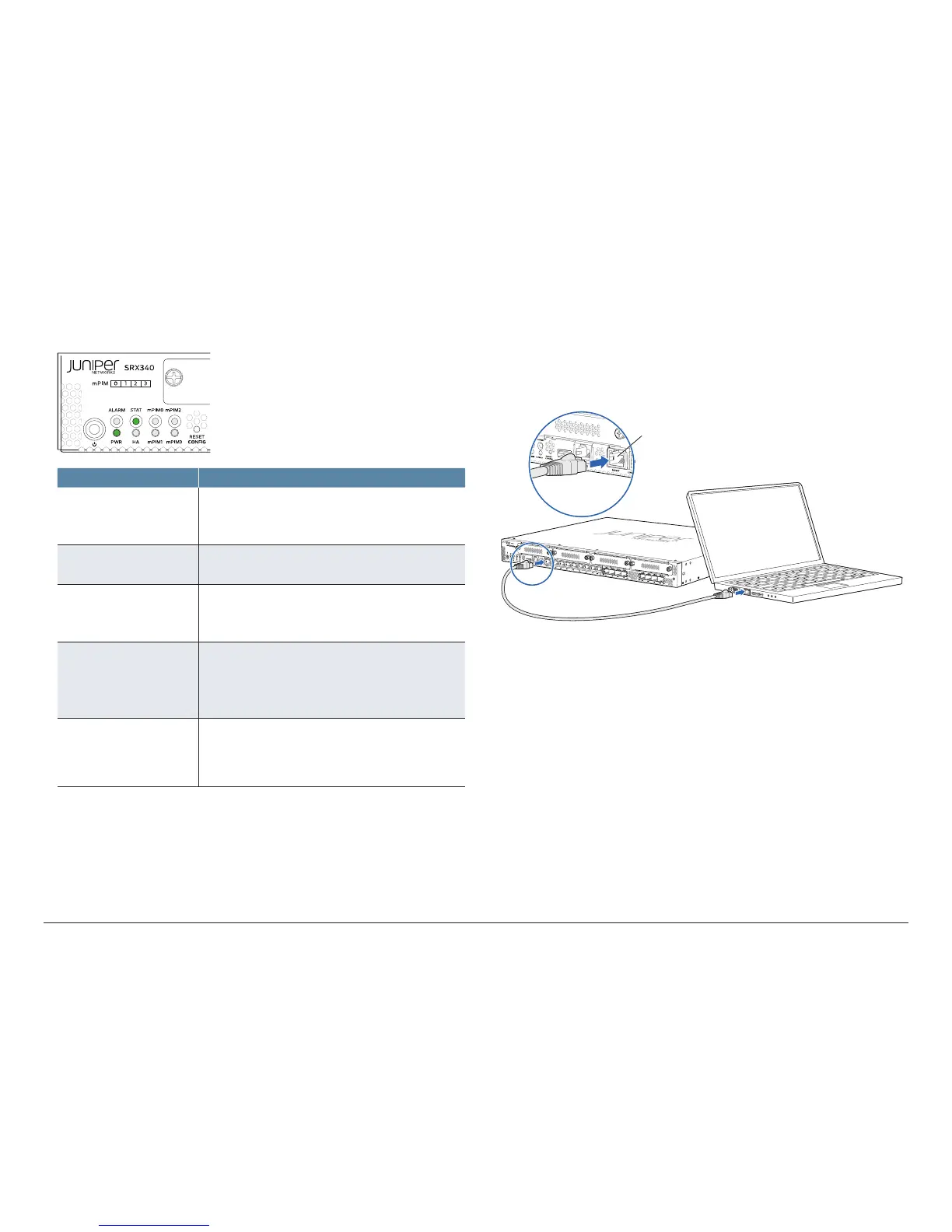
Connect the Management Device
1. To configure the device using J-Web (recommended), connect the
management port MGMT to the Ethernet port on the management device,
using an RJ-45 cable.
974
Management port
RJ-45 cable
Ethernet port
2. The services gateway functions as a DHCP server and automatically assigns
an IP address to the management device. Ensure that the management
device acquires an IP address on the 192.168.1.0/24 subnetwork from the
device.
If an IP address is not assigned to the management device, manually
configure an IP address in the 192.168.1.0/24 subnetwork. Do not assign
the 192.168.1.1 IP address to the management device, as this IP address is
assigned to the services gateway. By default, the DHCP server is enabled
on the fxp0 interface and L3 VLAN interface, irb.0 (interface ge-0/0/1 to
ge-0/0/15, which is configured with an IP address of 192.168.2.1/24).