NOTE: INPUT 0 and INPUT 1 on the three-input 240-A DC power supply in slot PEM0
must be powered by dedicated power feeds derived from feed A, and INPUT 0 and
INPUT 1 on the three-input 240-A DC power supply in slot PEM1 must be powered
by dedicated power feeds derived from feed B. This configuration provides the
commonly deployed A/B feed redundancy for the system.
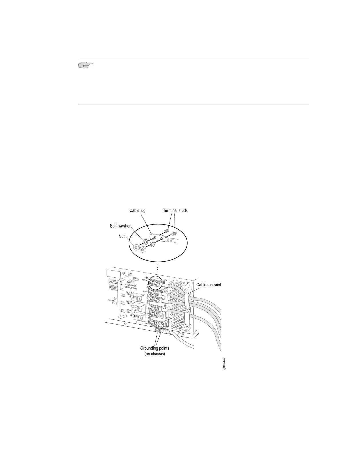
8. Loosen the captive screw or screws on the cable restraint on the right edge of
the power supply faceplate.
9. Route the DC power cables through the cable restraint.
10. Tighten the cable restraint captive screw or screws to hold the power cables in
place.
11. Verify that the power cabling is correct, that the power cables are not touching
or blocking access to other hardware components, and that they do not drape
where people could trip on them.
12. Replace the clear plastic cover over the terminal studs on the faceplate.
Figure 14: Connecting Power Cables to the Power Supply
16 ■ Connecting DC Power to a Three-Input 240-A Power Supply in a T640 Router
 Loading...


