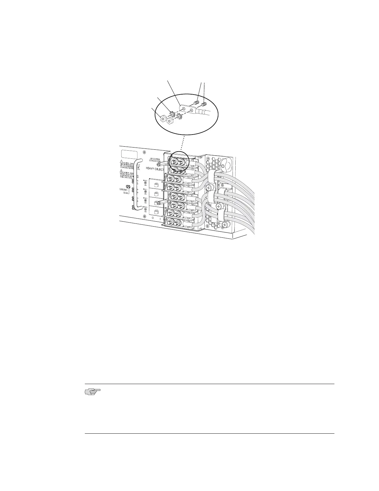
Figure 19: Connecting a Power Cable to a Four-Input 240-A DC Power Supply
g004661
Terminal studsCable lug
Locking
washer
Nut
11. Loosen the captive screws on the cable restraint on the right edge of the power
supply faceplate.
12. Route the DC power cables through the cable restraint.
13. Tighten the cable restraint captive screws to hold the power cables in place.
14. Verify that the power cabling is correct, that the power cables do not touch or
block access to other hardware components, and that they do not drape where
people could trip on them.
15. Replace the clear plastic cover over the terminal studs on the faceplate.
16. Switch on the customer site circuit breakers to provide voltage to the DC power
source cables.
17.
Verify that the INPUT PRESENT LEDs on the power supply faceplate are lit steadily,
indicating that the inputs are receiving power.
18.
Switch the circuit breakers on the power supply to the ON position (|).
NOTE: After a power supply is powered on, it can take up to 60 seconds for status
indicators—such as the LEDs on the power supply, the command output displays,
and messages on the LED display on the craft interface—to indicate that the power
supply is functioning normally. Ignore error indicators that appear during the first
60 seconds.
22 ■ Installing a T640 Four-Input 240-A DC Power Supply
 Loading...


