INSTALLATION, USE AND MAINTENANCE MANUAL – LC
Jurop SpA
Via Crosera n° 50
33082 Azzano Decimo, PN (Italia)
TEL. +39 0434 636811 FAX. +39 0434 636812
http://www.jurop.it
e-mail: info@jurop.it
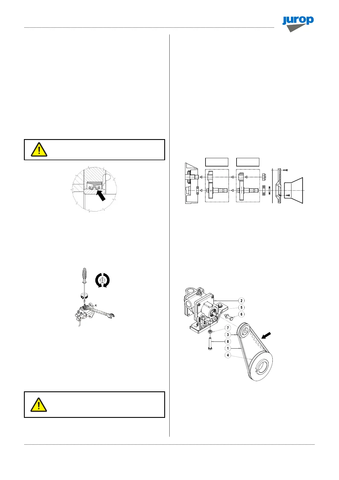
• Remove the screws (5) fixing the rear flange (6) and use the two
threaded holes to remove the flange – bearing – seal housing. If
necessary, hold the rotor by inserting a wooden block, protecting the
internal bearings from damage.
• Remove the bearing from the rear flange and replace the seal if
broken.
• Lubricate with oil the new vanes before inserting those inside each
groove of the rotor.
• Reinstall all the components in the following order: rear flange, seal
ring, bearing, compensation ring, gasket and flange with lubricating
pump (we recommend to fit correctly the pivot-key on the shaft groove).
• Tighten the nuts (pos. F) by means of a dynamometric wrench
adjusted at 88 Nm.
• Refill the cooling system and re-install the pipeline.
Do not damage components during assembly by
forcing them exceedingly.
• Do not flip the seal ring during rotation of the shaft. Do not leave
foreign objects inside the pump.
Adjusting the self-lubricating pump
• The automatic lubricating pump is adjusted by the manufacturer
before the shipping.
Pic. 6.8
• If consumption noticeably differs from the indicated value, adjust it
as follows:
− Remove the upper protection cover;
− Using a screwdriver and a 10 mm wrench, adjust the adjusting
screw (K). Close the nut and remount the upper protection cover;
− It is advisable to turn the screw of ¼ of turn and verify the actual
consumption.
Do not reduce oil consumption below the value
indicated in par. 2.3 (for functioning at speeds
different from the maximum, flow is proportionate
to rotating speed).
• ½ turn of the adjusting screw causes a variation in the flow of
approximately 40 - 80 g/h, depending on using conditions.
Replacing gear box components
• The pump with a 540 rpm gear box can be transformed into a
pump with a 1000 rpm gear box (and vice versa):
− Take down the gear box as illustrated. Remove also the drive
shaft’s pinion;
− Install the new pinion closing the nut;
− Mount the gear wheel including bearings and seals on the front
cover, properly aligning components. This housing may now be
installed in the gear box: fit the bearing in the internal housing on
the flange;
− Properly engage gears, replace the cover’s gaskets to complete
gear replacement. Insert the parallel pin, which maintains the
correct alignment;
• See picture below.
Cooling water pump belt tensioning
• To correctly tension the belt (1), after checking the alignment of
the two pulleys (3-4), loosen the screws (6) and the hexagon nut (7).
• Adjust the screw (8) that acts on the recirculation pump movement
(2) along the vertical axis.
• Once the belt is correctly tensioned (1), tighten the nut (7) and
screws (6).
• See the exploded view at the end of the manual for spare parts.
Pic. 6.9
 Loading...