α
α
1
α
α1
• Safety valves:
- Overpressure safety valve (pos. 5): mount it close to the pump. The valve
flow must prevent the LC pump from exceeding the absolute pressure of
2.0 bars or the maximum pressure allowed by the system. Do not apply
gate valves on the line;
- Vacuum control valve (pos. 6): install if necessary to limit the vacuum rate
of the system.
4.5. Cooling system
• It is composed of:
- Centrifugal recycle pump;
- Heat exchanger with electric fans operated by a thermostat;
- Expansion tank.
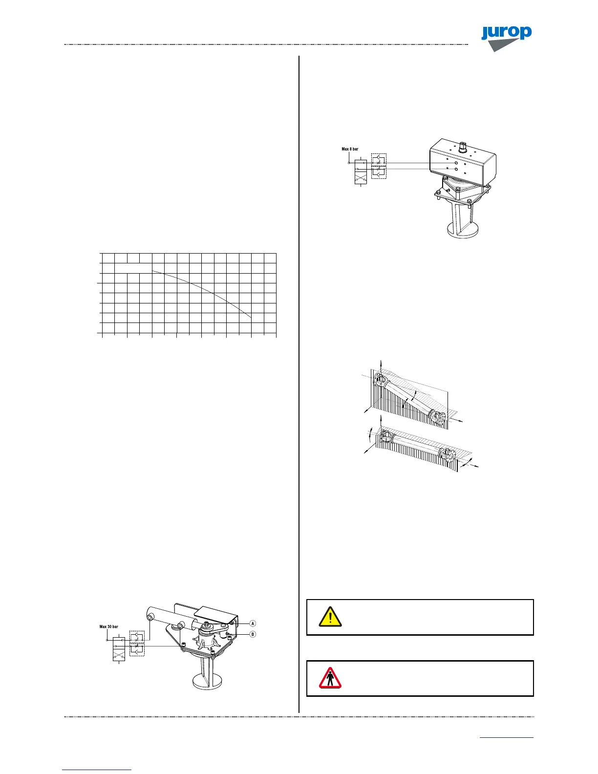
• The heat exchanger must dissipate the heat power indicated in
par. 2.2. The Fig. 4.3 shows the characteristic curve “Flow – Head” of
the recycle pump.
Pic. 4.3
• The cooling liquid temperature must not exceed 60° C. The air
flow generated by the exchanger fans must be kept free of obstacles.
4.6. Hydraulic actuator adjustment
• Extraordinary maintenance operations can require the upper cover
(and that of the actuator, either manual or pneumatic) to be removed.
We recommend ensuring enough space to carry out such operations.
• If the cock blocks or it moves with friction, screw up the clearance
regulation nut (A). Screw up ¼ of turn each time. Block the nut rotation
with the safety nut.
• The lubrication points (B) and the clearance regulation bolt (A)
must be accessible. See Fig. 4.5.
• Lubricate with grease every 1000 cycles. Grease type NLGI 2.
• It is suggested to install 2 one‐way flow controller between the
hydraulic switch and the hydraulic actuator. Set the flow controllers in
order to prevent hard hitting through the end of stroke. Minimum
commutation time: 1 second.
• Maximum feed pressure: 30 bar.
• To order spare parts see spare parts list at the end of this manual.
Pic. 4.4
4.7. Pneumatic actuator adjustment
• In the event of 4-way valves equipped with pneumatic actuator, we
recommend installing two one-way flow regulators between the
pneumatic “control” and the pneumatic actuator. The following figure
shows a schematic view of a possible pneumatic installation.
Pic. 4.5
• We recommend adjusting the two flow regulators in order for
rotation to occur without knocks and with a switching time of at least
one second.
4.8. Pump mounting - Drive connection
A) Cardan shaft drive
• Use telescopic cardan shafts.
Pic. 4.6
• In order to achieve a uniform motion of the driven shaft, the
following requirements must be met (see Fig. 4.6):
- Equal working angle α and α1 of both couplings.
- The internal fork joints must be coplanar.
- Both driven and driving shafts must be coplanar.
• It is also recommended working with limited articulated joint angles
(max 15° at 1000 rpm and max 11° at 1300 rpm) and disengaging the
transmission for those operations requiring great angles (steering or
lifting).
Follow the rotation direction as indicated on the
front flange. Follow the instructions of the cardan
shaft’s manufacturer.
• Use the protection that comes with the pump shaft.
Use the cardan protection supplied with the
pump. The pump installation must fulfil the
current EC injury prevention specifications.
 Loading...