1-18 (No.YA394)
4.8 ADJUSTMENT PROCEDURE
4.8.1 CHECK ITEM
4.8.2 TUNER / IF CIRCUIT
Item
Measuring
instrument
Test point Adjustment part Description
B1 VOLTAGE Signal
generator
DC voltmeter
TP-B1 : 1-pin
TP-E : 5-pin
(S1 connector)
[MAIN PWB]
(1) Receive a whole black signal.
(2) Connect a DC voltmeter to 1-pin and 5-pin of S1
connector.
(3) Make sure that the voltage is DC116.2V±2.0V.
Item
Measuring
instrument
Test point Adjustment part Description
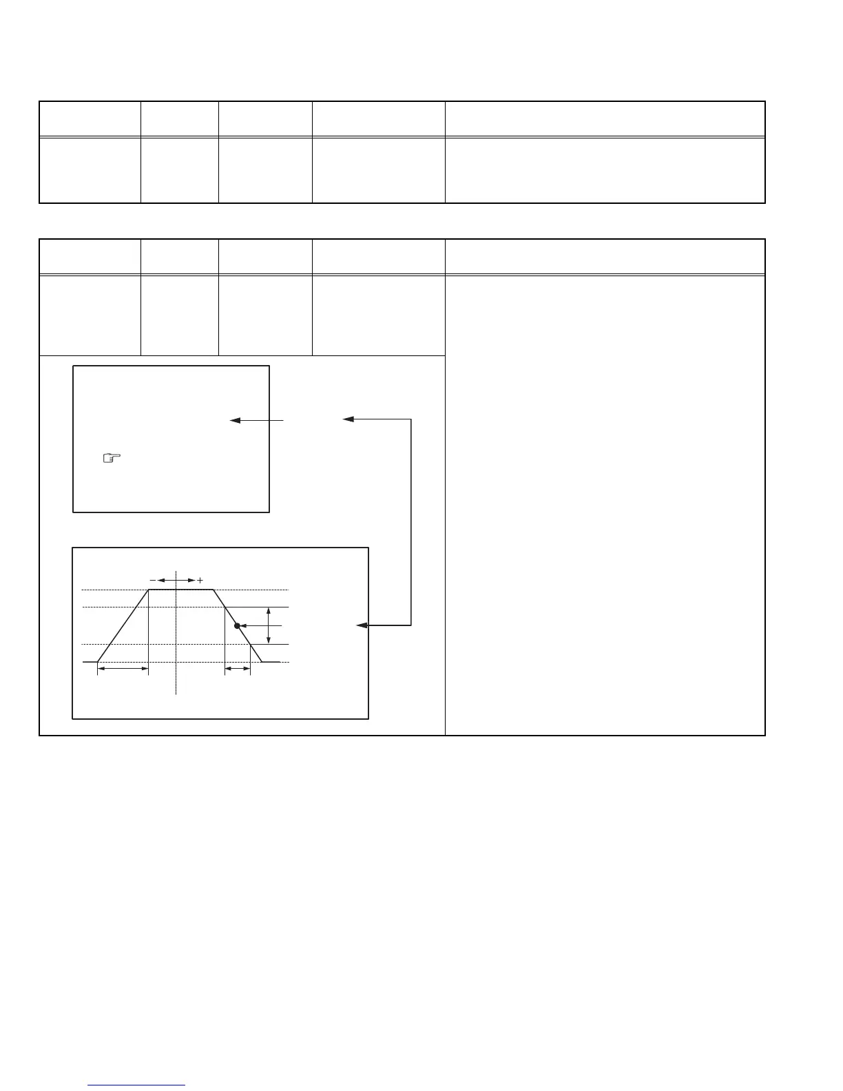
IF VCO Signal
generator
Remote
control unit
[1. IF]
1. VCO
• Please use a signal generator which frequency output is
correctly calibrated.
(1) Receive any broadcast.
(2) Select 1.IF from the SERVICE MENU.
(3) Select < 1.VCO >.
(4) Select VCO ADJUST with [MENU /] key.
(5) Press [MENU - / +] keys until the colour of the
characters TOO HIGH changes blue to yellow. Then
gradually press the [MENU - / +] keys until the TOO
LOW changes yellow. At this time, confirm that the
value of VCO ADJUST is near +00.
(6) Select AFT ADJUST with [MENU /] key.
(7) Press [MENU - / +] keys until the characters JUST
REFERENCE changes blue to yellow.
(8) Press the [DISPLAY] key three times to return to
normal screen.
VCO (CW)
***.**
MHz
TOO HIGH
ABOVE REFERENCE
JUST REFERENCE
BELOW REFERENCE
TOO LOW
AFT ADJUST
***
(
**
)
FINE
DISP : EXIT
VCO ADJUST
***
(
**
)
YELLOW
ADJUSTMENT AT THIS POINT
IS USELESS
ABOVE REFERENCE
TOO HIGH
BELOW REFERENCE
JUST REFERENCE
TOO LOW
ADJUSTMENT POINT
 Loading...