EN 9
GETTING STARTED
MasterPage: Start_Right
GETTING STARTED
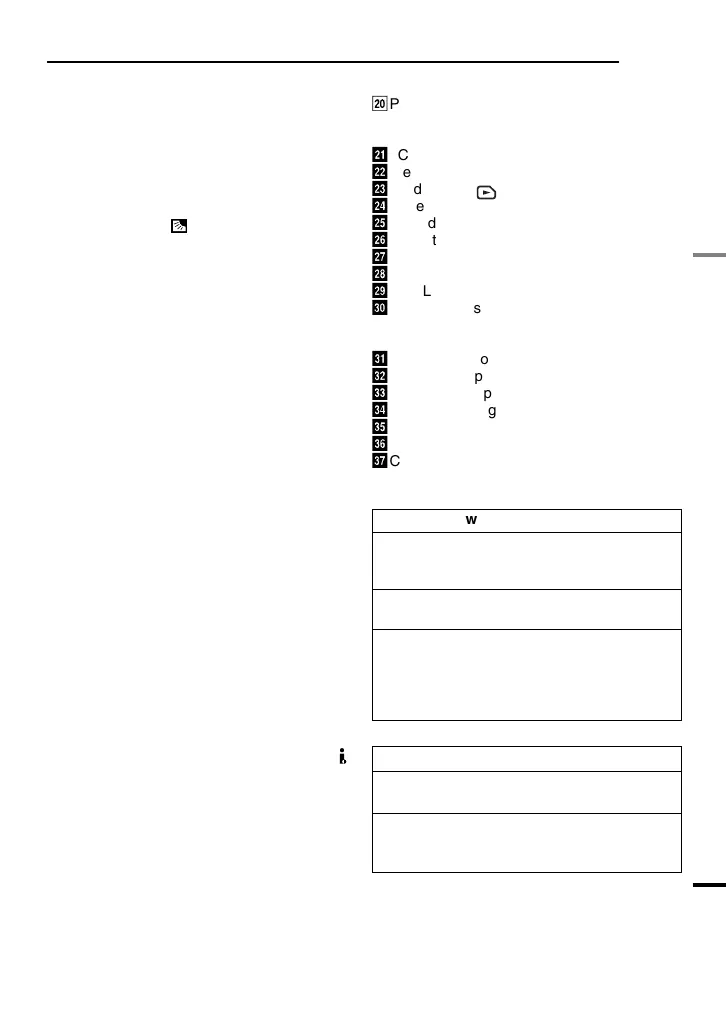
Controls
11 : Left/Rewind [1] ( pg. 21)/Quick
Review [QUICK REVIEW] ( pg. 18)
2 : Right/Fast-Forward [¡] ( pg. 21)/
LED Light [LIGHT] ( pg. 36)
3 : Up/Play/Pause [6] ( pg. 21)/Manual
Focus [FOCUS] ( pg. 37)
4 : Down/Stop[7] ( pg. 21)/Backlight
Compensation [ ] ( pg. 38)/
Spot Exposure ( pg. 38)/
Press down : SET
2VIDEO/MEMORY Switch
316:9 Wide Screen Button [16.9] ( pg. 17)
Blank Search [BLANK] ( pg. 22)
Index Button [INDEX] ( pg. 27)
4Menu Button [MENU] ( pg. 31)
5Data Battery Button [DATA] ( pg. 14)
6Auto Button [AUTO] ( pg. 20)
7Dioptre Adjustment Control ( pg. 15)
8Snapshot Button [SNAPSHOT]
( pg. 24, 33)
Live Slow Button [SLOW] ( pg. 33, 36)
9Power Zoom Lever [T/W] ( pg. 19)
Speaker Volume Control [VOL. +, –]
( pg. 21)
!Recording Start/Stop Button [START/STOP]
( pg. 18)
"Power Switch [REC, PLAY, OFF]
#Lock Button
$Battery Release Button [BATT.] ( pg. 13)
%Cassette Open/Eject Switch [OPEN/EJECT]
( pg. 16)
Connectors
&USB (Universal Serial Bus) Connector
( pg. 44)
(Digital Video Connector [DV IN/OUT]
(i.LINK*) ( pg. 43, 44)
* i.LINK refers to the IEEE1394-1995 industry
specification and extensions thereof. The
logo is used for products compliant with the
i.LINK standard.
)S-Video Output Connector [S] ( pg. 23)
The connectors are located beneath the
covers.
~Audio/Video Output Connector [AV]
( pg. 23, 42)
+DC Input Connector [DC] ( pg. 13)
Indicators
ä
POWER/CHARGE Lamp ( pg. 13)
Other Parts
ã
LCD Monitor ( pg. 8)
å
Viewfinder ( pg. 15)
ç
Card Cover [ ] ( pg. 17)
é
Battery Pack Mount ( pg. 13)
è
Shoulder Strap Eyelet ( pg. 12)
ê
Grip Strap ( pg. 12)
ë
Speaker ( pg. 21)
í
Lens
ì
LED Light ( pg. 36)
î
Camera Sensor
(Be careful not to cover this area, a sensor
necessary for shooting is built-in here.)
ï
Remote Sensor ( pg. 24)
ñ
Stereo Microphone
ó
Stud Hole ( pg. 15)
ò
Tripod Mounting Socket ( pg. 15)
ô
Cassette Holder Cover ( pg. 16)
ö
Memory Card Slot
õ
Connector Cover
Power Switch Position
REC:
To perform recording on the tape or in the
memory card.
OFF:
To switch off the camcorder.
PLAY:
● To play back a recording on the tape.
● To display a still image stored in the
memory card or to transfer a still image
stored in the memory card to a PC.
VIDEO/MEMORY Switch Position
VIDEO:
To record on a tape or play back a tape.
MEMORY:
To record in a memory card or access data
stored in a memory card.
GR-D770AG_EN.book Page 9 Tuesday, December 5, 2006 1:47 PM