1-9
Fig. C13
43
(S13)
42
(S13)
11
: 0.098 N·m (1.0 kgf·cm)
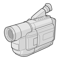
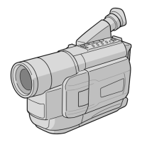
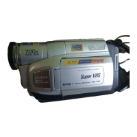
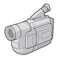
1.4 DISASSEMBLY/ASSEMBLY OF CAMERA SECTION
AND DECK SECTION
1.4.1 Flowchart of disassembly
The following flowchart shows the disassembly of the camera
section and deck section. When assembly of the camera
section and deck section, follow this flowchart in the reverse
order.
<Camera section/Deck section>
For details of disassembly of
manner, refer to page 1-12,
“1.5 REPLACEMENT OF
CCD IMAGE SENSOR.
▼
▼
▼
▼
▼
▼
(Only for
SXM930)
5 Frame assembly
6 Cassette housing assembly
▼
1
DSC board assembly
2
Zoom unit assembly
3 Main board assembly
4 OP block assembly
(Incl. CCD board assembly)
4 OP block assembly
4
CCD board assembly
1 DSC BOARD D1 2(S1), (L1a), (L1b), (L1c)
ASSEMBLY *CN 1a , 1b
HOLDER (DSC)
2 ZOOM UNIT D2 3(S2)
ASSEMBLY *CN 2a
4(S2)
*CN 2a
3 MAIN BOARD D3 (S3), (L3a), (L3b)
*CN 3a , 3b , 3c , 3d , 3e
3f , 3g , 3h
4 OP BLOCK D4 2(S4)
ASSEMBLY CUSHION (OP)
5 FRAME ASSEMBLY D5 (S5a), 2(S5b), (S5c)
6 CASSETTE D6 4(S6)
HOUSING
ASSEMBLY
1.4.2 Disassembly method
STEP
/LOC PART
NO.
REMOVAL
Fig.
No.
List of Abbreviations:
2(S1) = 2 Screws (S1)
4(L1a)=4 Locking Tabs (L1a)
CN=Connector
*UNLOCK/RELEASE/
UNPLUG/UNCLAMP/
UNSOLDER
 Loading...