This document serves as a service manual for the JVC GY-HM600U, GY-HM600E, GY-HM650U, and GY-HM650E HD Memory Card Camera Recorders. It provides detailed instructions for disassembly, adjustment, and troubleshooting, primarily intended for service personnel.
Function Description
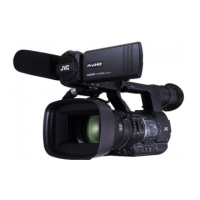
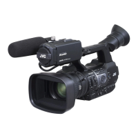
The JVC GY-HM600/650 series are HD Memory Card Camera Recorders designed for professional use. These cameras are capable of recording high-definition video onto SDHC/SDXC memory cards. They feature a Fujinon 23x zoom lens, a 1/3-inch Progressive CMOS image pickup device, and a 3-color separation prism for accurate color reproduction. The cameras support various recording formats, including QuickTime File Format (for Final Cut Pro), MP4, MXF (MPEG-2), and AVCHD (MPEG-4 AVC/H.264), offering flexibility for different production workflows. Audio recording is supported with Dolby Digital 2ch and LPCM 2ch options.
The GY-HM650U/E models offer additional features, including network connection capabilities via USB-A, allowing for advanced functionalities such as live streaming or file transfer over a network. Both series are equipped with multiple input/output terminals, including HD/SD SDI, HDMI, AV, and XLR audio inputs, catering to diverse professional needs.
Usage Features
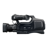
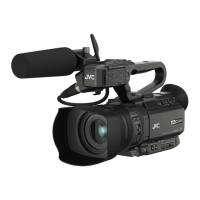
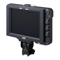
The camera recorders are designed with user-friendly features for professional operation. They include a 3.5-inch LCD monitor and a 0.45-inch LCOS viewfinder for monitoring. The lens offers a wide zoom range (4.1 mm to 94.3 mm, equivalent to 29 mm to 667 mm in 35 mm conversion), with an F1.6 aperture for low-light performance. Optical filters (OFF, 1/4, 1/16, 1/64) and gain settings (-6dB to 24dB, plus Lolux modes) provide extensive control over exposure. An electronic shutter with speeds from 1/6 to 1/10000 and variable frame rates (2/30-60/30fps, 2/25-50/25fps, 2/24-60/24fps) allow for creative control over motion.
The cameras support dual SDHC/SDXC card slots, enabling continuous recording or simultaneous recording for backup. The GY-HM650U/E models also incorporate GPS functionality, which can be accessed and adjusted through the service menus. The handle assembly includes various controls and input terminals, such as XLR inputs, for convenient audio management.
Maintenance Features
This service manual outlines several procedures for maintaining and servicing the JVC GY-HM600/650 series.
Disassembly: The manual provides step-by-step instructions for disassembling key sections of the camera, including:
- Center frame section: This involves removing the L side cover assembly, R side cover assembly, MAIN board, NETWORK board (GY-HM650 only), SDSLOT board, and the rear assembly. Specific screws (A, B, C, D, E, F, G, H, J, K) are identified for each step, along with instructions for disconnecting FFC wires and connectors (e.g., CN210, CN1412, CN3112, CN203, CN201, CN207, CN214, CN208, CN213, CN209, CN212, CN202, CN204, CN205, CN206, CN215, CN216, CN809).
- Lens unit: Instructions are provided for removing the board bracket and the lens unit itself, detailing the screws (M, N) involved.
- Handle assembly: This section covers the removal of the handle cover T, shoe spring, shoe, GPS (GY-HM650 only), HANDLE board, VF unit, and XLR board. Specific screws (A, B, C, D, E, F, G, H, J) and connectors (CN405, CN407, CN506, CN503, CN1806) are indicated.
- Monitor assembly and AVR board: This involves removing the joint cover, hinge cover, monitor assembly, front guard, OPE cover, volume knob, and the AVR board, with corresponding screws (K, L, M, N, P, Q, R, S) and connectors (CN301, CN305, CN302).
Adjustment: The manual details a specialized adjustment process using a PC and dedicated software (HM6xx_Adjust.exe). This includes:
- Preparation: Instructions for preparing an SD card with a "PROJECT.ADJ" file, connecting a JLIP cable to the AUX terminal, and setting up the camera for adjustment mode.
- Software operation: Guidance on launching the adjustment software, setting up a serial port, and navigating through various tabs for specific adjustments.
- Adjustment items: Comprehensive procedures for Composite signal adjustment (CGAIN, YGAIN, YSETUP, YSYNC for 60Hz U/I and 50Hz E), Zoom ring adjustment (ZOOM MR, FOCUS MR, ZOOM VR, Z Tracking), OIS adjustment (OIS Drv), Ingain adjustment, AF Filter adjustment (for ND 1/16 and ND 1/64), White Blemish adjustment (BPD), and Audio adjustment (XLR LINE/MIC levels, MIC BALANCE). Each adjustment specifies the required instruments (oscilloscope, color bar output, collimator, light source) and the steps to follow, often involving operating sliders in the software while observing waveforms or other indicators.
Troubleshooting (Service Menus): The manual describes how to access and operate various service menus for diagnostic and maintenance purposes:
- Accessing service menus: Instructions for entering service mode by holding down specific buttons (FOCUS ONE PUSH AUTO, MENU, USER1, USER2, USER3).
- Advanced Function menu: Allows adjustment of parameters like Pixel Compen Det (FA), FAW Sensitivity, Silent Zoom, AF Mode, AF Sensitivity, AF Frequency, C.Rec Audio Fade, Loop Rec, and SDI Out.
- Service Function menu: Provides access to Test Signal, FPGA1/2, FB1/2, DC Shutdown, BATT Shutdown, and BATT Alarm settings.
- DIP SW menu: Offers control over various internal DIP switches (System, IF, Network, CC, BE), though it notes these are for factory use only and should not be changed for repair or maintenance.
- Hour Meter menu: Displays and allows resetting of power, fan, and slot eject hour meters.
- Others menu: Provides access to ALL Reset and displays chassis and serial numbers.
Firmware Update: Detailed instructions are provided for updating the camera's firmware:
- Preparation: Copying the firmware file to an SD/SDHC memory card, ensuring proper formatting, and checking the directory structure.
- Update procedure: Turning on the camera while holding specific buttons (FOCUS PUSH AUTO, MENU/THUMB) to initiate the update, inserting the SD/SDHC card into slot B, and monitoring the progress on the VF screen. The manual also describes error messages ("Update Error!", "Update can't be Executed!") and their implications.
Safety Precautions: The manual emphasizes safety during servicing, including:
- Critical parts: Identifying parts critical for safety with a specific symbol and shaded area, requiring replacement only with specified part numbers.
- Fuse replacement: Caution for using only the same type and rated fuse(s).
- Wiring and insulation: Instructions for using specified internal wiring and insulating materials, and ensuring wires do not contact heat-producing or sharp parts.
- Power cord: Checking the power cord for secure attachment after replacement.
- CRT products (if applicable): Caution regarding high voltage circuits and X-ray emission standards.
- Crimp type wire connectors: Detailed procedure for replacing connectors, including stripping wires and proper crimping.
- Battery replacement: Warning about explosion risk if replaced with an incorrect type and instructions for proper disposal.
Safety Checks after Servicing: Procedures to ensure compliance with safety standards after repairs:
- Insulation resistance test: Checking resistance between power cord prongs and externally exposed parts.
- Dielectric strength test: Checking dielectric strength between power cord prongs and exposed accessible parts.
- Clearance distance: Confirming specified distances between soldered terminals and metallic parts.
- Leakage current test: Measuring leakage current between earth ground/power cord prongs and externally exposed accessible parts.
- Grounding (Class 1 models only): Checking grounding impedance between the earth pin in the AC inlet and exposed accessible parts.