1-8 (No.HC047<Rev.001>)
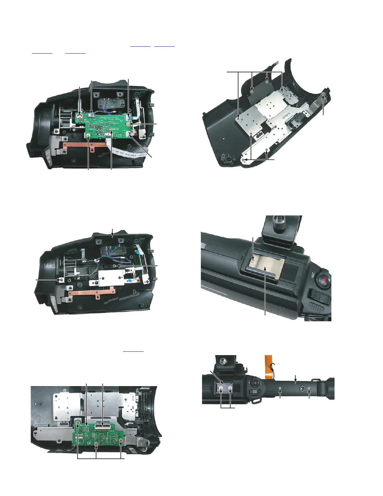
3.2.2 Removing the TC board (See Figure 2)
• Remove teh grip cover assembly.
(1) Pull out the wires from the connectors CN1212
, CN1211,
CN1213
and CN1214 on the TC board.
(2) Remove the two screws B attaching the TC board, and
then remove the TC board.
Fig.2
3.2.3 Removing the seesaw assembly (See Figure 3)
• Remove the grip cover assembly and TC board.
(1) Remove the two screws C attaching the seesaw assembly,
and then remove the seesaw assembly.
Fig.3
3.3 R Side cover assembly section
3.3.1 Removing the GAIN board (See Figure 1)
(1) Pull out the wire from the connector CN1413
on the GAIN
board.
(2) Remove the three screws A attaching the GAIN board, and
then remove the GAIN board.
Fig.1
3.3.2 Removing the R OPE unit (See Figure 2)
• Remove the GAIN board.
(1) Remove the eight screws B attaching the R OPE unit, and
then remove the R OPE unit.
Fig.2
3.4 Handle assembly section
3.4.1 Removing the handle cover T (See Figure 1, 2 and 3)
(1) Remove the one screw A attaching the shoe spring, and
then remove the shoe spring.
Fig.1
(2) Remove the two screws B attaching the shoe, and then re-
move the shoe.
(3) Remove the two screws C attaching the handle cover T.
Fig.2
CN1214
CN1213
CN1211
B TC Board
B
CN1212
C
C
Seesaw assembly
A
CN1413GAIN Board
B
B
B
R OPE Unit
R OPE Unit
A
Shoe spring
B
CC
Handle cover T
Shoe

 Loading...