(No.HC047<Rev.001>)1-9
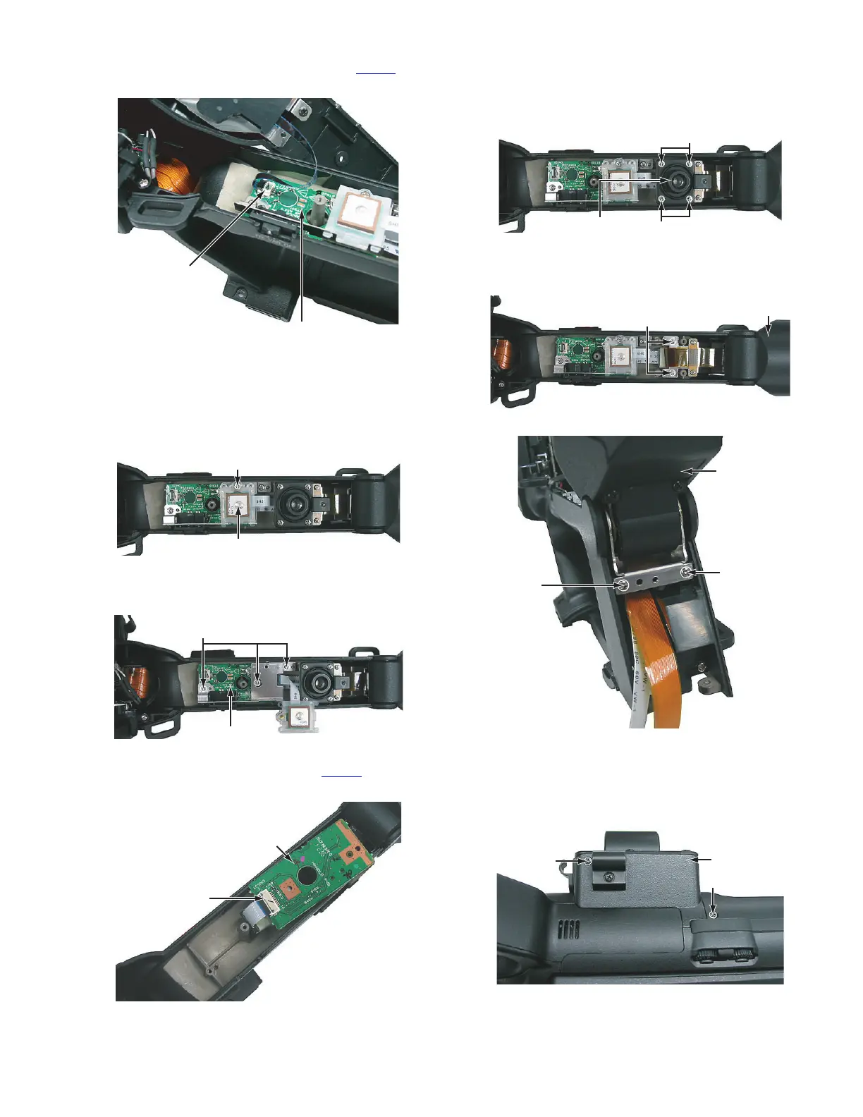
(4) Pull out the FFC wire from the connector CN405 on the
HANDLE board, and then remove the handle cover T.
Fig.3
3.4.2 Removing the GPS and HANDLE board (See Figure 4,
5 and 6)
• Remove the handle cover T.
(1) Remove the one screw D attaching the GPS. (only GY-
HM650)
Fig.4
(2) Remove the three screws E attaching the bracket and
HANDLE board.
Fig.5
(3) Pull out the wire from the connector CN407
on the HAN-
DLE board, and then remove the GPS and HANDLE board.
Fig.6
3.4.3 Removing the VF unit (See Figure 7, 8 and 9)
• Remove the handle cover T.
(1) Remove the four screws F attaching the ACC base, and
then remove the ACC base.
Fig.7
(2) Remove the four screws G attaching the VF unit, and then
remove the VF unit.
Fig.8
Fig.9
3.4.4 Removing the XLR board (See Figure 10, 11, 12 and
13)
• Remove the handle cover T.
(1) Remove the six screws H attaching the XLR cover.
Fig.10
CN405
HANDLE Board
D
GPS
E
HANDLE Board
CN407
HANDLE Board
F
F
ACC Bace
G
VF Unit
G
G
VF Unit
H
H
XLR Cover

 Loading...