1-10 (No.HC047<Rev.001>)
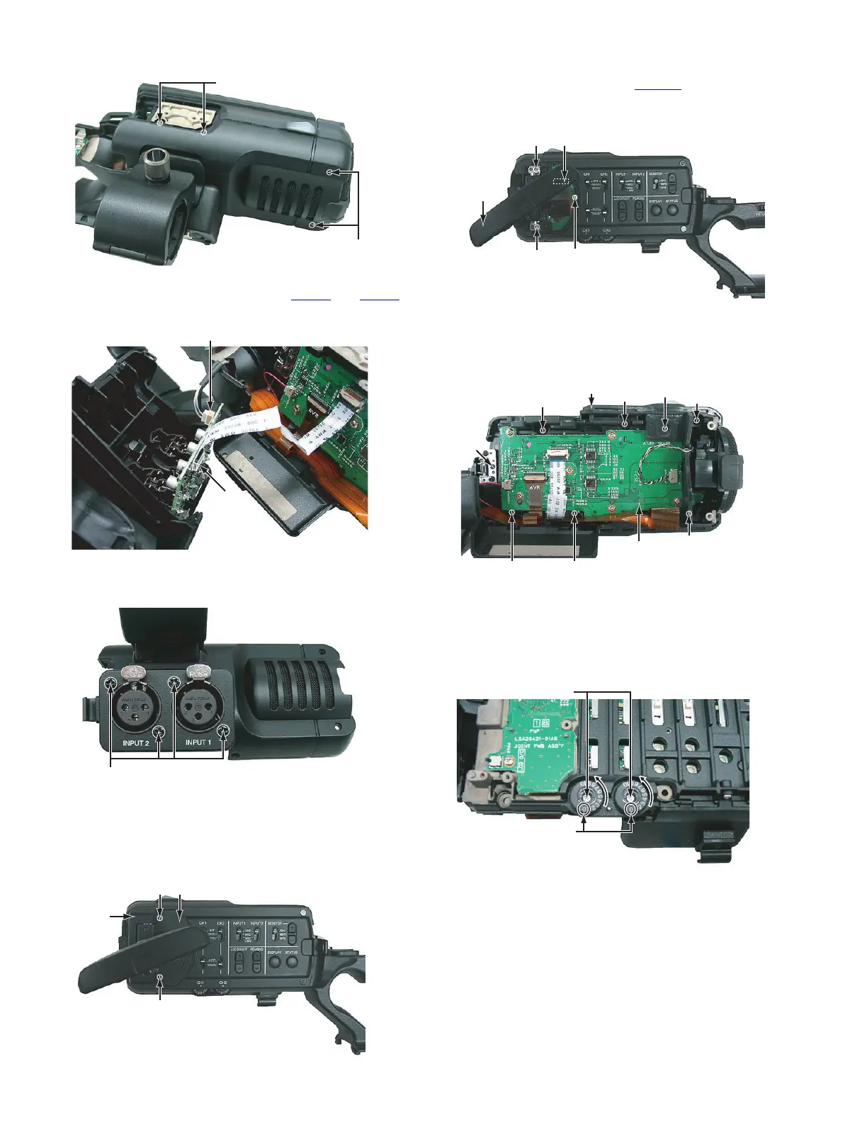
Fig.11
(2) Pull out the wires from the connectors CN506
and CN503
on the XLR board.
Fig.12
(3) Remove the four screws J attaching the terminal, and then
remove the XLR board.
Fig.13
3.4.5 Removing the monitor assembly and AVR board (See
Figure 14, 15, 16, 17 and 18)
(1) Remove the two screws K attaching the joint cover, and
then remove the joint cover and hinge cover.
Fig.14
(2) Remove the one screw L attaching the FFC, and then pull
out the wire from the connector CN1806
.
(3) Remove the two screws M attaching the hinge, and then
remove the monitor assembly.
Fig.15
(4) Remove the one screw N, and then remove the front guard.
(5) Remove the six screws P and the one screw Q attaching
the OPE cover, and then remove the OPE cover.
Fig.16
(6) Remove the two screws R attaching the volume knob, and
then remove the volume knob.
• When attaching the volume knob, turn in the direction of
an arrow, and attach so that “0” becomes a position of a
figure.
Fig.17
H
H
CN506
CN503
J
Hinge
cover
K Joint cover
K
M
Monitor
assembly
CN1806
L
M
Q
P
P
P
P
PP
N
Front guard
AVR Board
R
"0"

 Loading...