(No.HC047<Rev.001>)1-7
Fig.13
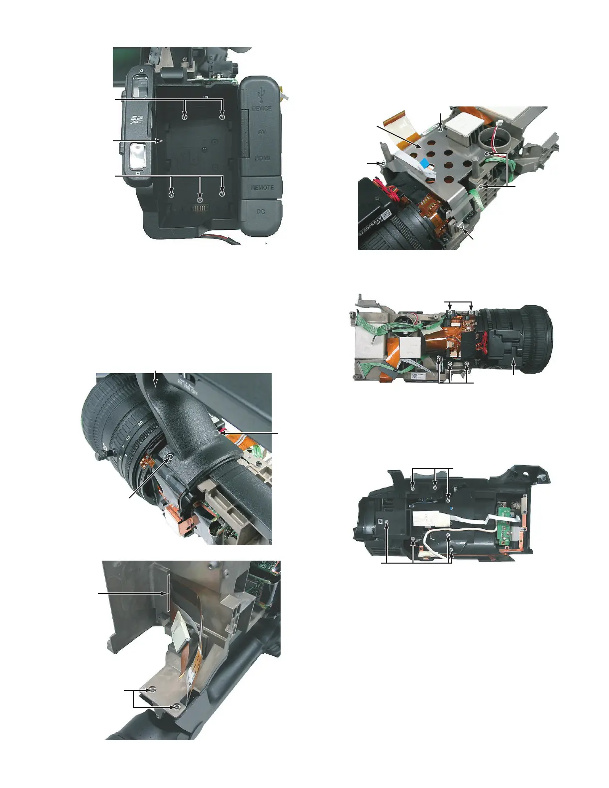
3.1.6 Removing the handle assembly (See Figure 14 and
15)
• Remove the L side cover assembly and R side cover assembly
etc, .
(1) Remove the four screws L attaching the handle assembly,
and then remove the handle assembly.
• When attaching the handle assembly, let two wires from
VF pass to the slit of a frame.
Fig.14
Fig.15
3.1.7 Removing the lens unit (See Figure 16 and 17)
• Remove the L side cover assembly and R side cover assembly
etc, .
(1) Remove the five screws M attaching the board bracket,
and then remove the board bracket.
Fig.16
(2) Remove the five screws N attaching the lens unit, and then
remove the lens unit.
Fig.17
3.2 L Side cover assembly section
3.2.1 Removing the Grip cover assembly (See Figure 1)
(1) Remove the seven screws A attaching the grip cover as-
sembly, and then remove the grip cover assembly.
Fig.1
K
K
Rear
assembly
Handle assembly
L
L
Slit
L
M
Board
bracket
M
M
M
N
N
Lens unit
A
A

 Loading...