EasyManuals Logo

JVC KD-Lh401 Service Manual

JVC KD-Lh401
141 pages
To Next Page IconTo Next Page
To Previous Page IconTo Previous Page
Page #23 background imageLoading...
Page #23 background image
(No.MA063)1-23
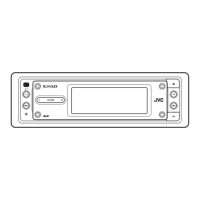
3.2.13 Removing the select arm R / link plate
(See Figs.27 and 28)
Prior to performing the following procedure, remove the top
plate assembly.
(1) Bring up the select arm R to release from the link plate
(joint a') and turn as shown in the figure to release the two
joints b' and joint c'.
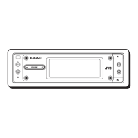
(2) Move the link plate in the direction of the arrow to release
the joint d'. Remove the link plate spring at the same time.
REFERENCE:
Before removing the link plate, remove the mode sw..
Fig.27
Fig.28
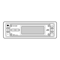
3.2.14 Reattaching the Select arm R / link plate
(See Figs.29 and 30)
REFERENCE:
Reverse the above removing procedure.
(1) Reattach the link plate spring.
(2) Reattach the link plate to the link plate spring while joining
them at joint d'.
(3) Reattach the joint a' of the select arm R to the first peak of
the link plate while joining the two joints b' with the slots.
Then turn the select arm R as shown in the figure. The top
plate is joined to the joint c'.
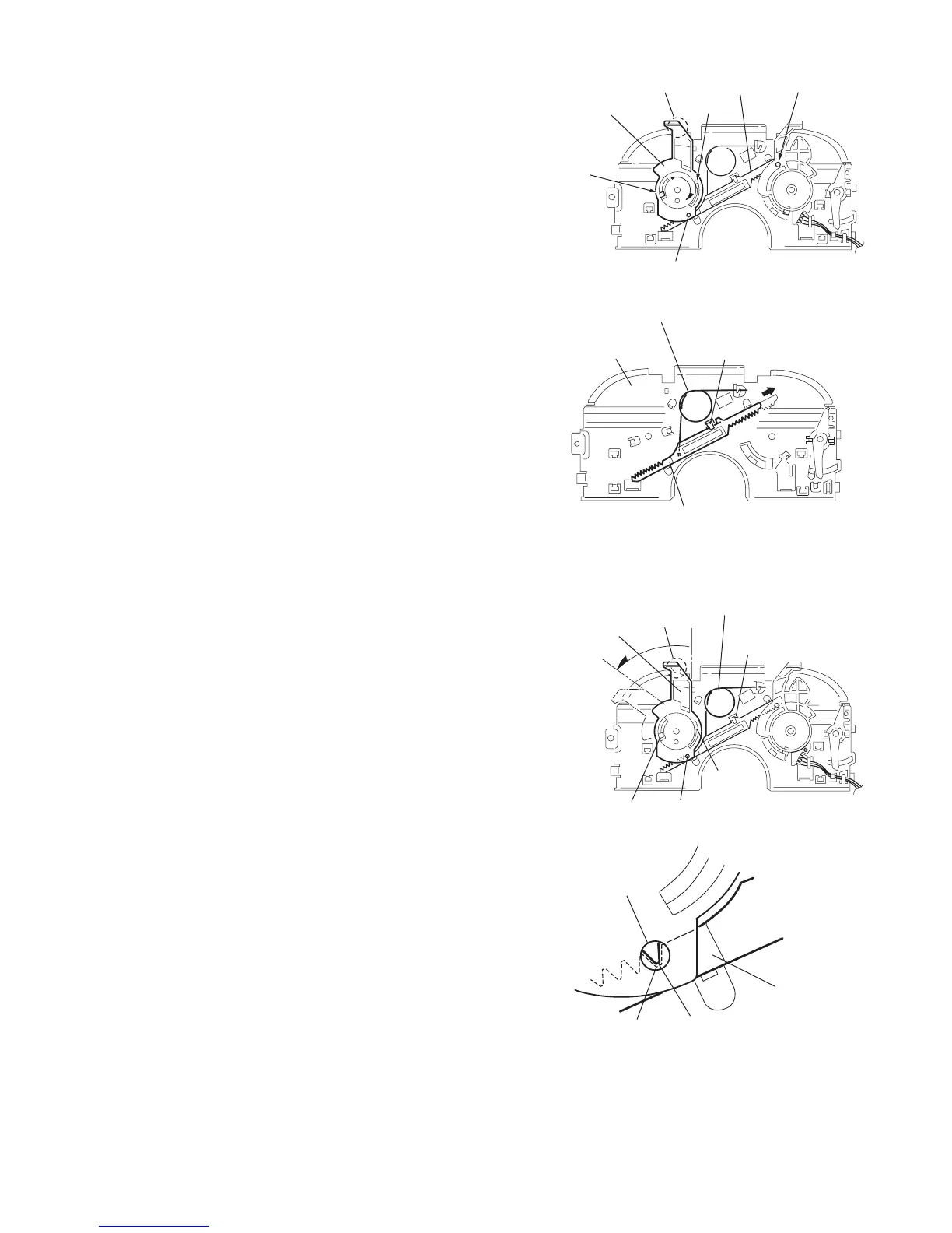
CAUTION:
When reattaching the select arm R, check if the points e'
and f' are correctly fitted and if each part operates prop-
erly.
Fig.29
Fig.30
Joint r
Link plate
Joint b'
Joint b'
Joint c'
Select arm R
Joint a'
Top plate
Link plate
Link plate spring
Joint d'
Select arm R
Joint c'
Joint d'
Link plate spring
Joint b'
Joint b'
Joint a'
Link plate
Joint a'
Point e'
Point f'

Table of Contents

Other manuals for JVC KD-Lh401

Questions and Answers:

Question and Answer IconNeed help?

Do you have a question about the JVC KD-Lh401 and is the answer not in the manual?

JVC KD-Lh401 Specifications

Audio Amplifier Specifications IconAudio Amplifier Specifications
maximum power output front50 W per channel
maximum power output rear50 W per channel
continuous power output RMS front19 W per channel into 4 Ω, 40 Hz to 20 000 Hz at no more than 0.8% total harmonic distortion
continuous power output RMS rear19 W per channel into 4 Ω, 40 Hz to 20 000 Hz at no more than 0.8% total harmonic distortion
load impedance4 Ω (4 Ω to 8 Ω allowance)
equalizer control range frequencies60 Hz, 150 Hz, 400 Hz, 1 kHz, 2.4 kHz, 6 kHz, 12 kHz
equalizer control range level±10 dB
frequency response40 Hz to 20 000 Hz
signal-to-noise ratio70 dB
line-out level/impedance5.0 V/20 kΩ load (full scale)
output impedance1 kΩ
CD Player Specifications IconCD Player Specifications
operating voltageDC 14.4 V (11 V to 16 V allowance)
allowable operating temperature0°C to +40°C
dimensions (W × H × D) installation size182 mm × 52 mm × 159 mm
dimensions (W × H × D) panel size188 mm × 58 mm × 12 mm
mass1.6 kg (excluding accessories)
frequency response5 Hz to 20 000 Hz
dynamic range96 dB
signal-to-noise ratio98 dB
max. bit rate mp3320 Kbps
max. bit rate wma192 Kbps
Tuner Specifications IconTuner Specifications
frequency range FM87.5 MHz to 108.0 MHz
frequency range AM (MW)522 kHz to 1 620 kHz
frequency range AM (LW)144 kHz to 279 kHz
usable sensitivity FM11.3 dBf (1.0 µV/75 Ω)
50 dB quieting sensitivity FM16.3 dBf (1.8 µV/75 Ω)
alternate channel selectivity FM (400 kHz)65 dB
frequency response FM40 Hz to 15 000 Hz
stereo separation FM30 dB
capture ratio FM1.5 dB
sensitivity MW20 µV
selectivity MW35 dB
sensitivity LW50 µV

Related product manuals