(No.MA465<Rev.003>)1-11
SECTION 3
DISASSEMBLY
3.1 Main body (Used figure were KD-R418J)
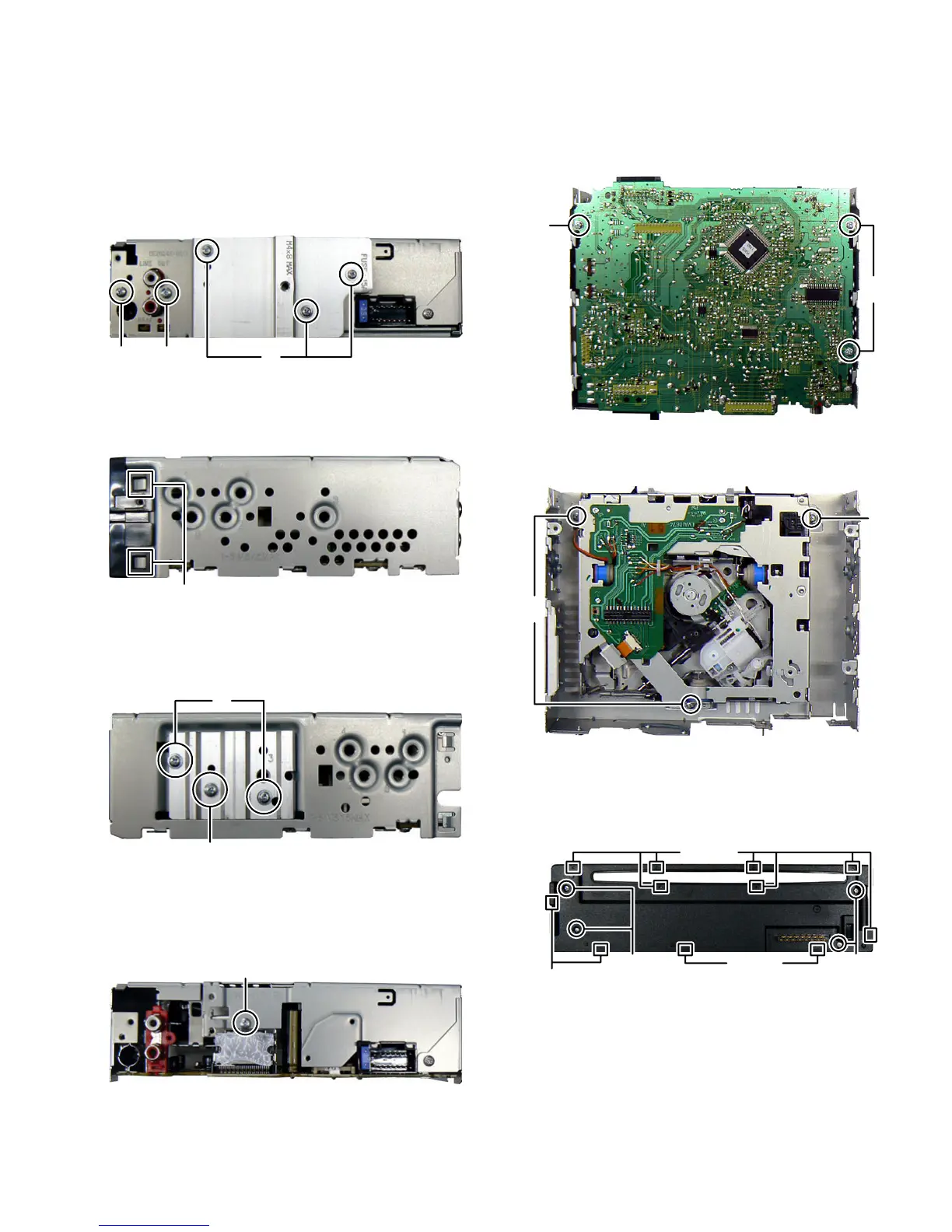
3.1.1 Removing the Bottom chassis (See Fig.1)
(1) Remove the three screws A attaching the Heat sink.
(2) Remove the one screrw B and one screw C attachiong the
Bottom chassis.
Fig.1
3.1.2 Removing the Front chassis (See Fig.2)
(1) Disengage four hooks a engaged both side of the Frot
chassis.
Fig.2
3.1.3 Removing the Side plate (See Fig.3)
(1) Remvoe the two screws D and one screw E attaching the
Side plate.
Fig.3
3.1.4 Removing the Main board (See Fig.4, 5)
(1) Remove the one screw F attaching the main board. (See
Fig.4)
Fig.4
(2) Remove the three screws G attaching the Main board.
(See Fig.5)
Fig.5
3.1.5 Removing the CD mechanism (See Fig.6)
(1) Remove the three screws H attaching the CD mechanism.
Fig.6
3.1.6 Removing the Switch board (See Fig.7)
(1) Remove the Volume knob.
(2) Remove the four screws J attaching the Rear cover.
(3) Disengage eleven hooks b engaged Rear cover.
Fig.7
ABC
hook a
D
E
F
G
G
H
H
JJ
hook b
hook b
hook b
 Loading...