1-12 (No.MA465<Rev.003>)
3.2 CD MECHANISM assembly section
• Remove the CD MECHANISM assembly from the main body.
3.2.1
Removing the MECHANISM CONTROL BOARD
assembly (See Fig.
1
and
2
)
(1)
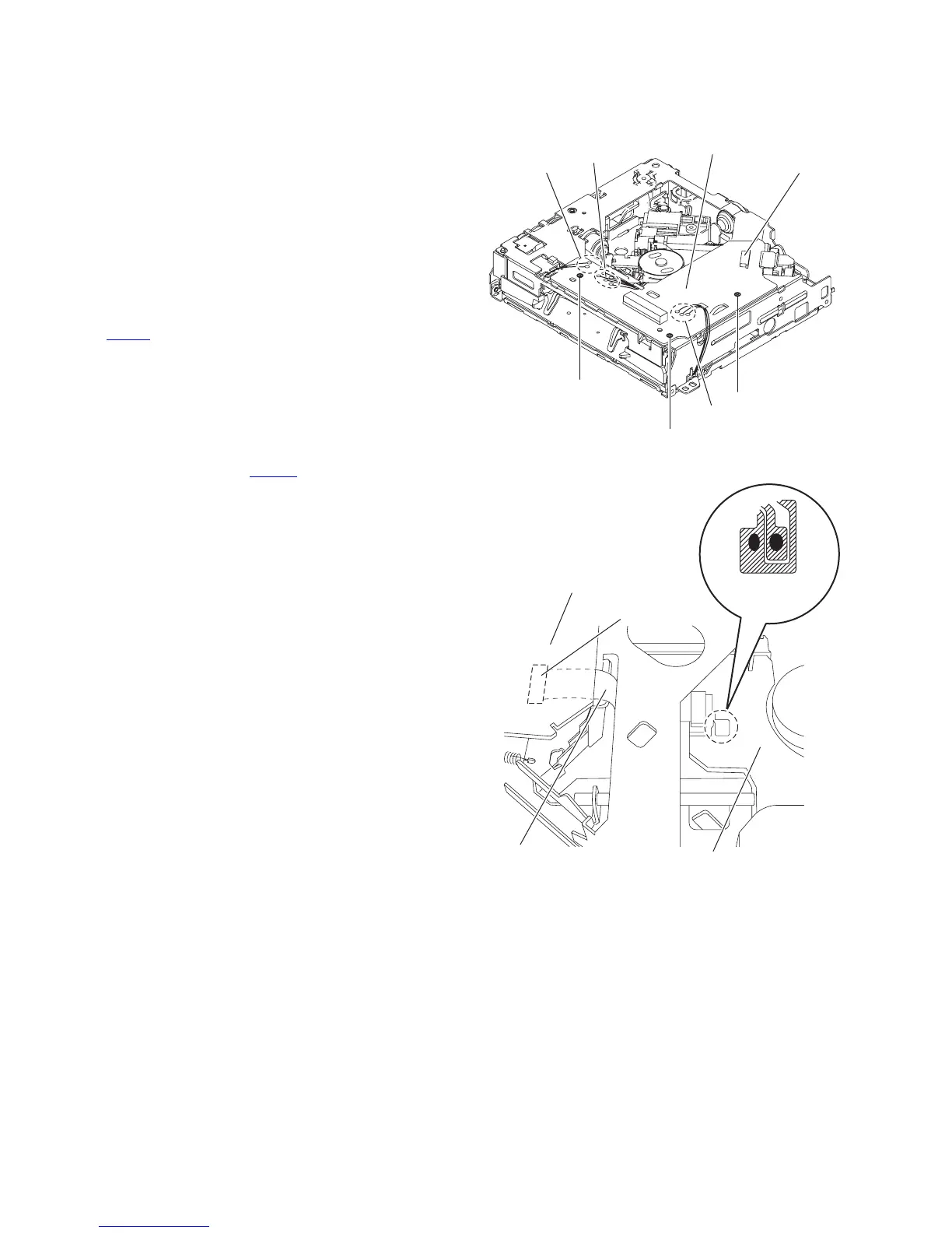
From the bottom side of CD MECHANISM assembly,
remove the solders from the soldered sections (
a
,
b
and
c
) on the MECHANISM CONTROL BOARD assembly.
(See Fig.
1
.)
(2) Remove the three screws A attaching the MECHANISM
CONTROL BOARD assembly. (See Fig.1.)
(3) Solder the short land sections on the pickup. (See Fig.2.)
Caution:
• Solder the short land sections on the pickup before
disconnecting the flexible wire from the connector
CN102
on the MECHANISM CONTROL BOARD as-
sembly.
If the card wire is disconnected without attaching
solder, the pickup may be destroyed by static
electricity. (See Fig.
2
.)
•
When attaching the MECHANISM CONTROL
BOARD assembly, remove the solders from the
short land sections after connecting the flexible
wire to the connector CN102
on the MECHANISM
CONTROL BOARD assembly.
Fig.1
Fig.2
A
CN102
Mechanism
control board
A
A
b
a
c
Mechanism control board
CN102
Pickup
Flexible wire
Short land section