Do you have a question about the JVC KD-R35E and is the answer not in the manual?
General safety guidelines regarding chassis burrs and laser beam.
Measures to prevent static discharge damage to the optical pickup and yourself.
Warnings and precautions for handling laser radiation and safety switches.
Steps for removing bottom chassis, front chassis, side plate, main board, CD mechanism, and switch board.
Detailed steps for disassembling the CD mechanism, including control board, top cover, rollers, and internal parts.
Lists required instruments, measuring conditions, volume settings, and dummy load usage.
Details on entering service mode, operating keys, and specific modes like RUNNING and CHECK.
Information on DC offset errors, error codes, and their distinctions for troubleshooting.
Specific procedures and information related to the tuner service mode, including RDS data.
Wiring diagram for the 16-pin connector, detailing connections for various models.
| Brand | JVC |
|---|---|
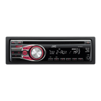
| Model | KD-R35E |
| Category | Car Receiver |
| Language | English |