1-18 (No.MA465<Rev.003>)
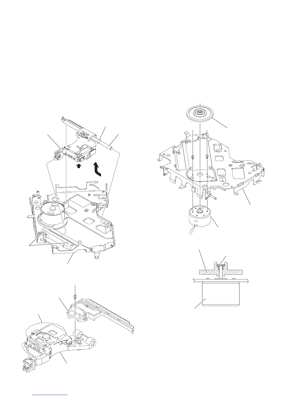
3.2.13 Removing the pickup assembly (See Fig.21 to 22)
• Remove the MECHANISM CONTROL BOARD assembly, top
cover, mechanism section, clamper assembly and feed motor
assembly.
Caution:
• Do not touch section u on the pickup assembly. (See Fig.21
and 22.)
(1) From the bottom side of the T.M chassis assembly, move
the pickup assembly in the direction of the arrow from the
T.M chassis assembly. (See Fig.21.)
(2) Pull out the main shaft. (See Fig.21.)
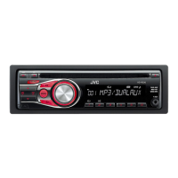
(3) Remove the screw K attaching the pickup to the rack plate.
(See Fig.22.)
Reference:
When attaching the loading motor, apply grease to the
sections s and t. (See Fig.21.)
Fig.21
Fig.22
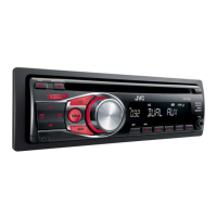
3.2.14 Removing the spindle motor (See Fig.23 and 24)
•
Remove the MECHANISM CONTROL BOARD assembly,
top cover, mechanism section, clamper assembly, feed motor
assembly and pickup assembly.
(1) From the top side of the T.M chassis assembly, remove the
CD T.table assembly from the spindle motor. (See Fig.23.)
(2) Remove the two screws L attaching the spindle motor.
(See Fig.23.)
(3) Take out the spindle motor from the bottom side of the T.M
chassis assembly. (See Fig.23.)
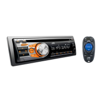
Reference:
When attaching the CD T.table assembly to the spindle
motor shaft, apply loctite 460 to inside the CD T.table
assembly. (See Fig.
24
.)
Fig.23
Fig.24
s
u
t
Main shaft
Pick up assembly
T.M. chassis assembly
u
Rack plate
Pick up
K
CD T.table assembly
T.M.chassis assembly
Spindle motor
LL
CD T.table assembly
Spindle motor
Loctite