(No.MA465<Rev.003>)1-17
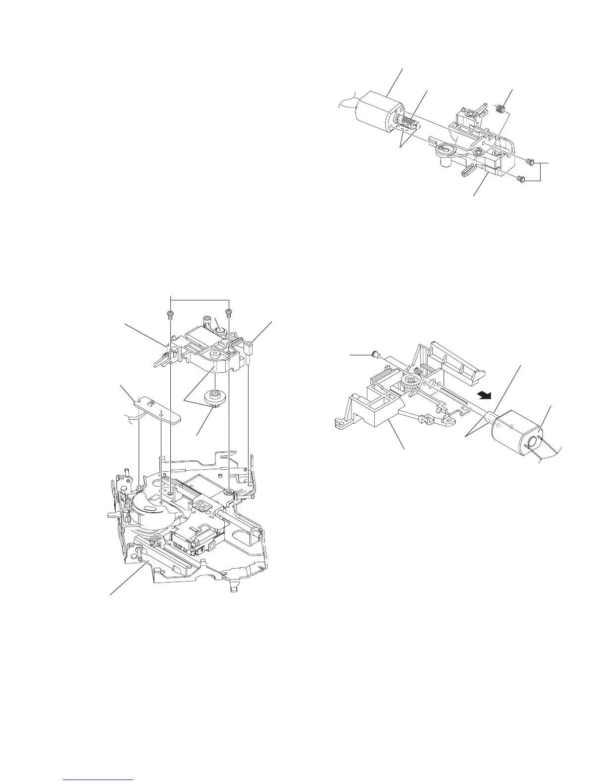
3.2.10 Removing the feed motor (See Fig.18 and 19)
• Remove the MECHANISM CONTROL BOARD assembly, top
cover, mechanism section and clamper assembly.
(1) From the bottom side of the T.M chassis assembly, remove
the two screws G attaching the feed motor assembly. (See
Fig.18.)
(2)
Remove the two screws
H
attaching the feed motor to
f.motor holder. (See Fig.
19
.)
Reference:
When attaching the f. wheel gear, trigger arm and feed
motor, apply grease to the sections (n, p and q). (See
Fig.18 and 19.)
3.2.11 Removing the SWITCH BOARD assembly (See
Fig.18)
• Remove the MECHANISM CONTROL BOARD assembly, top
cover, mechanism section, clamper assembly and feed motor
assembly.
From the bottom side of the T.M chassis assembly, take out
the SWITCH BOARD assembly in an upward direction from
T.M chassis assembly.
Fig.18
Fig.19
3.2.12 Removing the loading motor (See Fig.20)
• Remove the MECHANISM CONTROL BOARD assembly, top
cover, mechanism section and clamper assembly.
(1) From the right side of the L.M base assembly, remove the
two screws J attaching the loading motor.
(2) Take out the loading motor in the direction of the arrow
from the L.M base assembly.
Reference:
When attaching the loading motor, apply grease to the
section r.
Fig.20
n
Feed motor assembly
Switch board
F.wheel gear
T.M. chassis assembly
Trigger arm
p
G
q
Comp. spring
F.motor holder
H
F.worm gear
Feed motor
r
Loading moto
L.M. base assembly
J
L.worm gear