1-16 (No.MA465<Rev.003>)
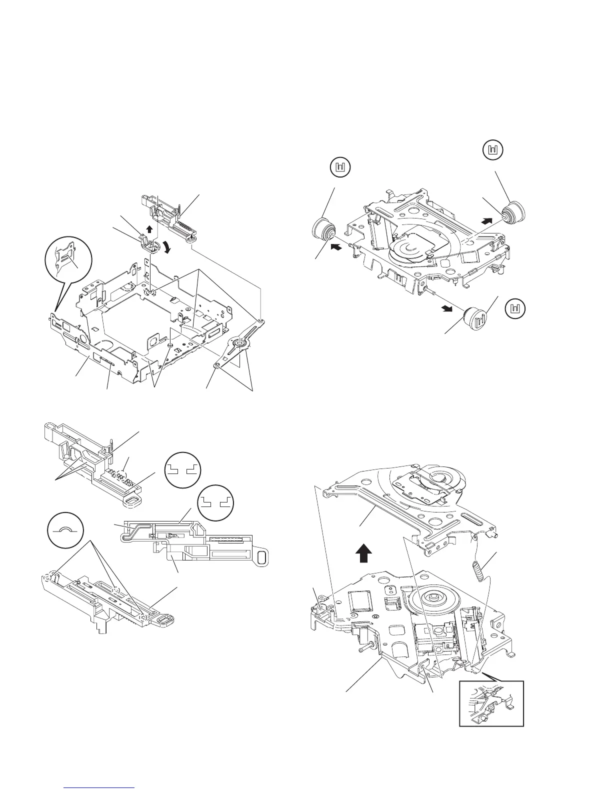
3.2.7 Removing the F.lock lever and slide cam (R) (See
Fig.14 and 15)
• Remove the MECHANISM CONTROL BOARD assembly, top
cover and mechanism section.
(1) From the top side of the mecha frame, take out the slide
cam (R) assembly in an upward direction. (See Fig.14.)
(2) Rotate the F.lock lever in the direction of the arrow 1, and
then take out the direction of the arrow 2. (See Fig.14.)
Reference:
When attaching the slide cam (R) assembly, the f.lock
lever and the link arm apply grease to the section
h
.
(See Fig.
14
and
15
.)
Fig.14
Fig.15
3.2.8 Removing the damper (See Fig.16)
• Remove the MECHANISM CONTROL BOARD assembly, top
cover and mechanism section.
From the mechanism section, pull out the three dampers in the
direction of the arrow.
Reference:
Before inserting the shaft to the dampers, apply IPA to the
pocket j of damper.
Fig.16
3.2.9 Removing the clamper assembly (See Fig.17)
• Remove the MECHANISM CONTROL BOARD assembly, top
cover and mechanism section.
(1) From the top side of the mechanism section, release the
clamper spring.
(2) Move the clamper assembly in the direction of the arrow,
and then release the joints (k and m).
(3)
Take out the clamper assembly from the T.M chassis
assembly.
Fig.17
h
h
h
h
h
h
Mecha frame
Link arm
F.lock lever
2
1
Slide cam(R) assembly
Slide cam(R) assembly
h
h
h
h
h
h
Slide cam(R) assembly
j
j
j
Damper (Brown)
Damper (Brown)
Damper (Gray)
k
m
Clamper assembly
Clamper spring
T.M. chassis assembly