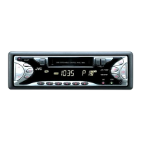
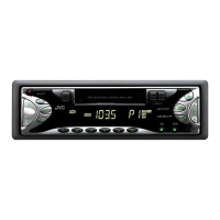
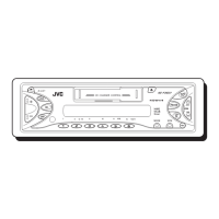
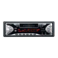
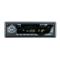
1-14 (No.MA094B)
Information for using a car audio service jig
(1) We're advancing efforts to make our extension cords common for all car audio products.
Please use this type of extension cord as follows.
(2) As a U-shape type top cover is employed, this type of extension cord is needed to check operation of the mechanism assembly
after disassembly.
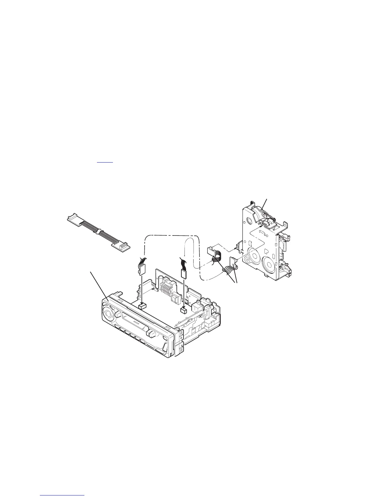
(3) Extension cord : EXTKSRT002-6P ( 6 pin extension cord ) For connection between mechanism assembly3. Extension cord :
EXTKSRT002-6P ( 6 pin extension cord ) For connection between mechanism assembly and main board.
(4) Check for mechanism driving section such as motor ,etc.
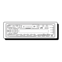
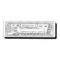
Disassembly method
(1) Remove the front panel assembly.
(2) Remove the bottom cover.
(3) Remove the front chassis assembly.
(4) Remove the heat sink.
(5) Remove the main board.
(6) Reattach the heat sink with the screw B. (Refer to Disassembly method.)
(7) Reattach the front panel assembly.
(8) Confirm that current is being carried by connecting an extension cord jig.
NOTE:
Available to connect to the CJ701
connector when installing the front panel.
CAUTION :
Be sure to attach the heat sink on the power amplifier IC of a main board when supplying the power.
If voltage is applied without attaching the heat sink, the power amplifier IC will be destroyed by heat.
Front Panel assembly
EXTKSRT002-6P
Extension cord
: EXTKSRT002-6P
Main board
Cassette mechanism
 Loading...