KS-F363R/KS-F360R
1-7
Prior to performing the following procedures, remove
the head amplifier board, the relay board and the
mechanism bracket.
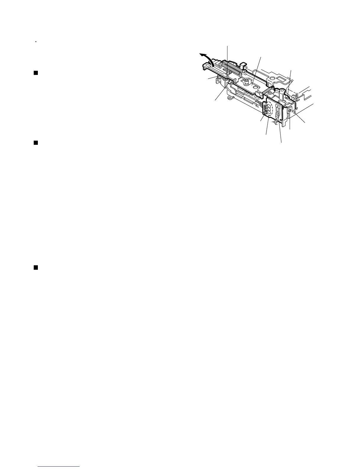
<Cassette mechanism assembly>
Unsolder the three wires a on the direction switch
board.
Remove the one screw A attaching the direction
switch board.
1.
2.
Removing the direction switch board
(See Fig.1)
Remove the screw B attaching the FF / REW lever
assembly on the back of the cassette mechanism
assembly.
Remove the screw C on the upper side of the FF /
REW lever assembly.
Lift and pull forward the FF / REW lever assembly to
disengage the joints b, c, d and e.
1.
2.
3.
Removing the FF / REW lever assembly
(See Fig.1)
Reattach the FF / REW lever assembly to the joint c
on the back of the chassis.
Reattach the pinch-roller shaft e, the change lever d
and the return link e to the chassis.
1.
2.
Reattaching the FF / REW lever assembly
(See Fig.1)
C
FF / REW lever assembly
Joint c
Joint b
B
A
Direction switch board
Joint d
Joint e
Soldering a
Fig.1
 Loading...