KS-F363R/KS-F360R
1-8
Prior to performing the following procedure, remove
the direction switch board and the FF / REW lever
assembly.
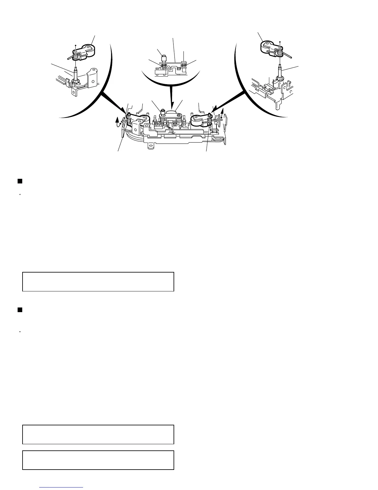
Remove the screw D attaching the playback head.
Remove the C washer and pull out the FF roller.
Remove the S support plate, the A arm spring (a)
and (b), the playback head.
1.
2.
3.
Removing the playback head (See Fig.2)
The A arm spring (a) differs from the A
arm spring (b).
ATTENTION:
Prior to performing the following procedure, remove
the direction switch board and the FF / REW lever
assembly.
Remove the P arm spring (f) in the pinch-roller (F)
assembly from the chassis.
Remove the P arm spring (r) in the pinch-roller (R)
assembly from the chassis.
Draw out the pinch roller (F) and (R) assembly from
the shaft.
1.
2.
3.
Removing the pinch-roller (R) and (F)
assembly (See Fig.2)
The P arm spring (f) differs from the P
arm spring (r).
ATTENTION:
The pinch roller (F) assembly differs
from the pinch roller (R) assembly.
ATTENTION:
A arm spring (b)
A arm spring (a)
Pinch-roller (R) assembly
Pinch-roller (F) assembly
Shaft
Shaft
S support plate
D
C washer
P arm spring (f)
P arm spring (r)
Remove the P arm spring (f)
from the chassis.
Remove the P arm spring (r)
from the chassis.
Playback head
FF roller
Fig.2
 Loading...