1-22
KS-FX711/KS-FX511
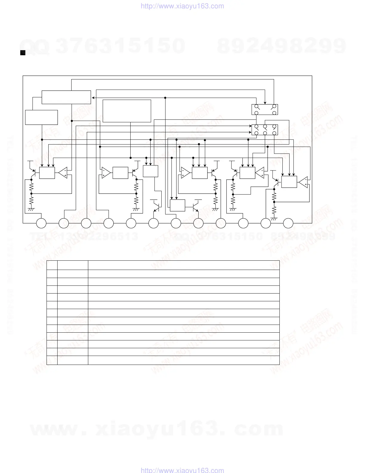
AN80T05 (IC901) : Power regulator
1.Terminal layout & Block diagram
2.Pin function
Pre
Drive
Thermal
Protection
Reference Voltage
Pre
Drive
AMP
Out
ASO & Peak
Current Protection
AMP
Out
Pre
Drive
Pre
Drive
Pre
Drive
1 2 3 4 5 6 7 8 9 10 11 12
ILL
10V
MODE2 MODE1 STB VDD
5.6V
AMP VCC ANT COM
8.7V
AM
8.7V
FM
8.7V
GND
1
2
3
4
5
6
7
8
9
10
11
12
ILL10V
TUNER
FM/AM
PWR-CNT
5.6V
REMOTOE
MEMORY
NC
9V
AMVCC
FMVCC
GND
10V power supply for illumination.
When 5V is input,becomes AM. and the antenna output is turned on.
When 5V is input,becomes AM. and the output of FM is switched.
When 5V is input, outputs to ILL,COM,and AMP. It is 0V usually.
5.6V power supply.
Power supply supply to remote amplifier
Back up. connects with ACC with it.
8.7V power supply.
The power supply of 8.7V to AM.
The power supply of 8.7V to FM.
Ground
Pin
No.
Symbol Function
Description of major ICs
w
w
w
.
x
i
a
o
y
u
1
6
3
.
c
o
m
Q
Q
3
7
6
3
1
5
1
5
0
9
9
2
8
9
4
2
9
8
T
E
L
1
3
9
4
2
2
9
6
5
1
3
9
9
2
8
9
4
2
9
8
0
5
1
5
1
3
6
7
3
Q
Q
TEL 13942296513 QQ 376315150 892498299
TEL 13942296513 QQ 376315150 892498299
http://www.xiaoyu163.com
http://www.xiaoyu163.com
 Loading...