1-10 (No.YA180)
SECTION 3
DISASSEMBLY
3.1 SYSTEM SETTEING
When the DIGITAL SIGNAL PWB is replaced or the DIGITAL
INPUT is not normal, SYSTEM SETTING in the following
procedure.
(1) Set to 0 minutes using the [SLEEP TIMER] key.
(2) Press the [VIDEO STATUS] key and [DISPLAY] key
simultaneously, then enter the SERVICE MODE.
(3) When the Main Menu is displayed, press [2] key to enter
the self check mode.
(4) Turn off the power by pressing the [POWER] key on the
remote control unit.
3.2 DISASSEMBLY PROCEDURE
NOTE:
• Make sure that the power cord is disconnected from the
outlet.
• Pay special attention not to break or damage the parts.
• When removing each board, remove the connectors as
required. Taking notes of the connecting points (connector
numbers) makes service procedure manageable.
• Make sure that there is no bent or stain on the connectors
before inserting, and firmly insert the connectors.
MAIN MENU SCREEN
SELF CHECK MODE SCREEN
LOB OK FAN OK
SYNC M:OK S:OK HD:NG
TIM OK
MSM OK DIGI 0000
MEM OK AVSW OK
YC OK AIO OK
TUN OK GCR NG 1
IP OK RGB OK 8
DVI OK HDMI OK
SERVICE MENU
1.ADJUST
2.SELF_CHK
3.I2C STOP
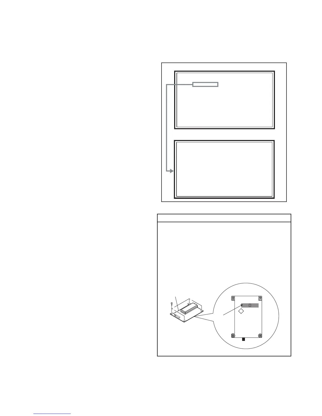
CAUTION AT DISASSEMBLY
• Pay extra attention in the following matter when turning the
power on with the REAR COVER removed.
(1) Prior to disassembly, unplug the power cord from the AC
outlet without fail. (Turn the power "off".)
(2) Make sure that the RECEIVER PWB: IC3102 is
completely covered with black masking tape. (Fig.1)
(3) Make sure to remove the masking of RECEIVER
PWB: IC3102 when attaching the REAR COVER.
(4) Do not turn the power on until the REAR COVER is
attached properly, after the masking is removed.
Fig.1
RECEIVER PWB
IC3101
IC3102
SOLDER SIDE
Masking tape
 Loading...