1-12 (No.MB160)
3.1.4 Removing the rear cabinet
(See Figs.15 to 17.)
• Prior to performing the following procedures, remove the top
cabinet.
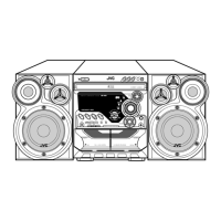
(1) From the right side of the main body, disconnect the wires
from the connector ACW3
on the amplifier board. (See
Fig.15.)
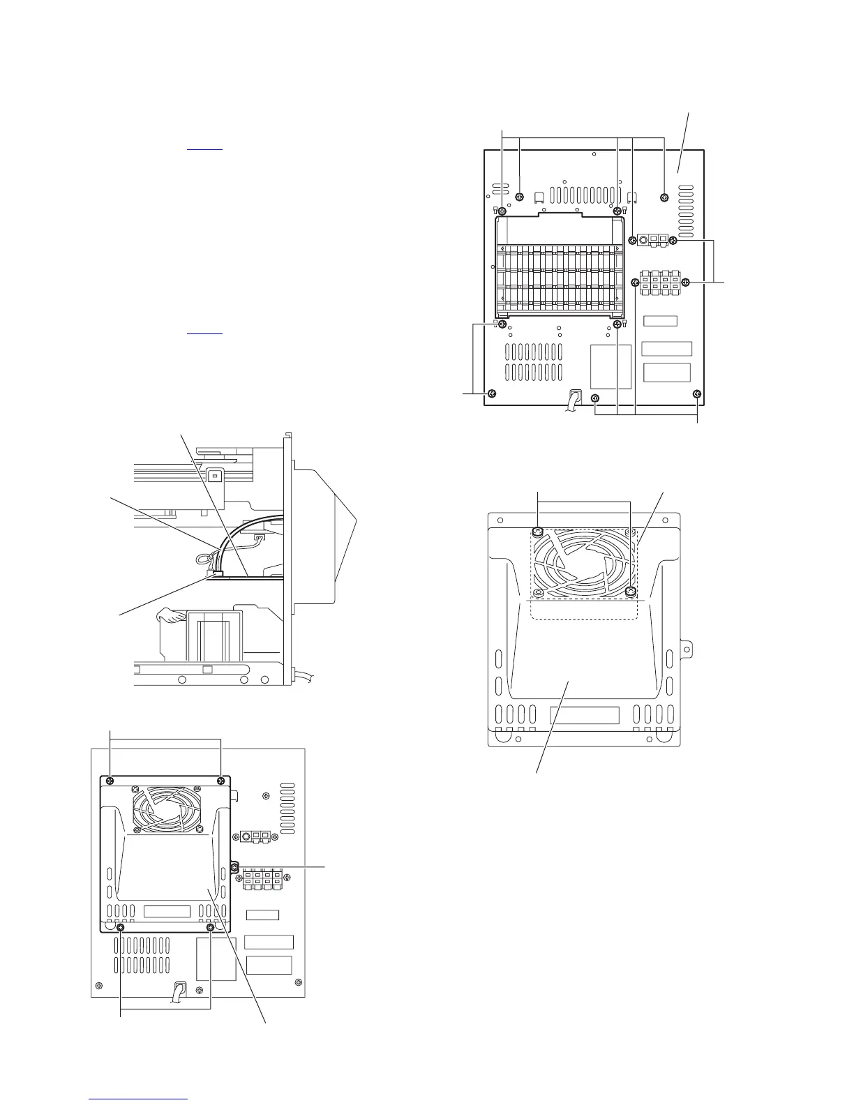
(2) From the back side of the main body, remove the five
screws K attaching the heat sink cover. (See Fig.16.)
(3) Remove the thirteen screws L attaching the rear cabinet.
(See Fig.17.)
3.1.5 Removing the fan motor
(See Figs.15, 16 and 18)
• Prior to performing the following procedures, remove the top
cabinet.
(1) From the right side of the main body, disconnect the wires
from the connector ACW3
on the amplifier board. (See
Fig.15.)
(2) From the back side of the main body, remove the five
screws K attaching the heat sink cover. (See Fig.16.)
(3) From the back side of the heat sink cover, remove the two
screws M attaching the fan motor. (See Fig.18.)
Fig.15
Fig.16
Fig.17
Fig.18
Amplifier board
Wire
CW3
Heat sink cover
K
K
K
Rear cabinet
LL
L
L
L
Heat sink cover
Fan moto
M

 Loading...