(No.MB160)1-13
3.1.6 Removing the amplifier board
(See Figs.19 and 20)
• Prior to performing the following procedures, remove the top
cabinet and CD changer mechanism assembly.
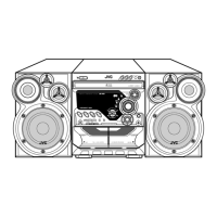
(1) From the top side of the main body, disconnect the wires
from the connectors (ACW2
, ACW3, ACW4) on the ampli-
fier board. (See Fig.19.)
Reference:
After connecting the wires to the connectors (ACW2
,
ACW3
), fix the wires with the wire holders as before.
(See Fig.19.)
(2) Disconnect the card wire from the connector ACW1
on the
amplifier board. (See Fig.19.)
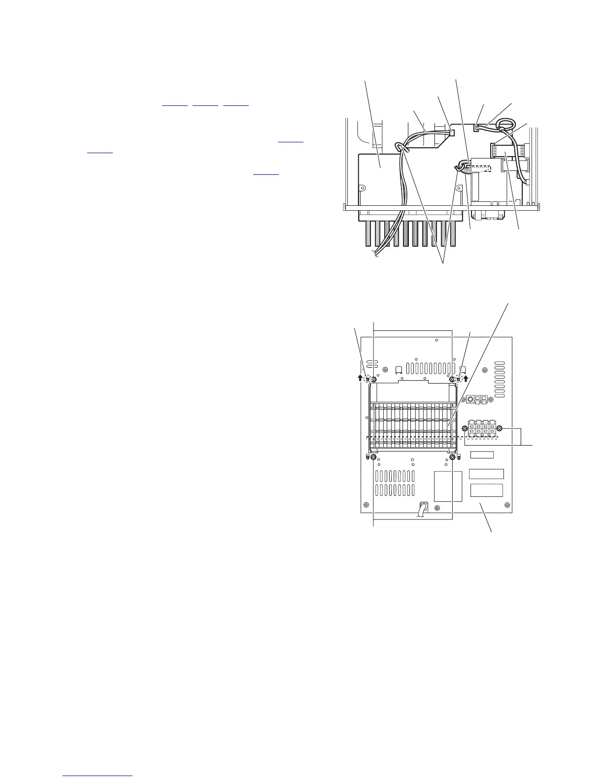
(3) From the back side of the main body, remove the six
screws N attaching the amplifier board. (See Fig.20.)
(4) Release the claws (c, d) from the rear cabinet and take out
the amplifier board from the inside of the main body. (See
Fig.20.)
Fig.19
Fig.20
ACW3
ACW4
Wire
Wire
Wire holders
ACW2
ACW1
Amplifier board
Cord wire
Wire
Amplifier board
Rear cabinet
N
N
N
d
c

 Loading...