1-14 (No.MB160)
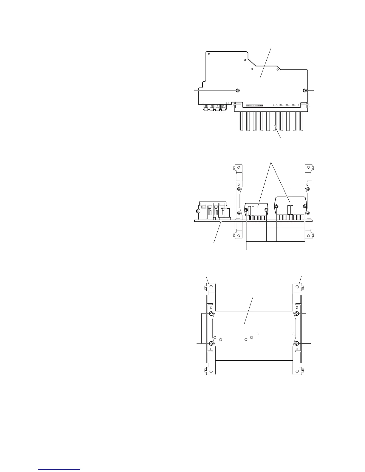
3.1.7 Removing the heat sink
(See Figs.21 to 23)
• Prior to performing the following procedures, remove the top
cabinet, CD changer mechanism assembly and amplifier
board.
(1) From the reverse side of the amplifier board, remove the
two screws P attaching the heat sink. (See Fig.21.)
(2) From the forward side of the amplifier board, remove the
four screws Q attaching the power amplifier IC on the heat
sink. (See Fig.22.)
(3) From the bottom side of the heat sink, remove the four
screws R attaching the brackets on the heat sink. (See
Fig.23.)
Fig.21
Fig.22
Fig.23
Amplifier board
Heat sink
P
P
Q
Amplifier board
Power amplifier IC
R
R
Heat sink
BracketBracket

 Loading...