1-16 (No.MB160)
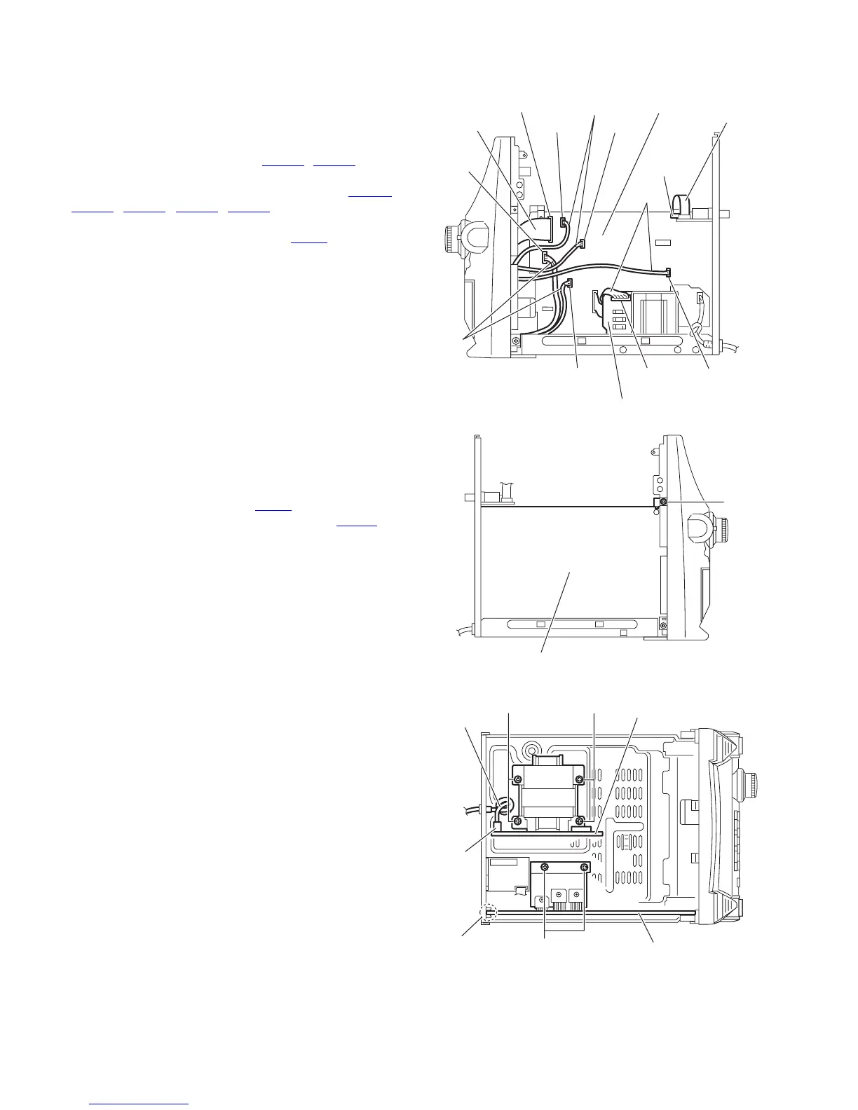
3.1.9 Removing the main board
(See Figs.26 to 28)
• Prior to performing the following procedures, remove the top
cabinet, CD changer mechanism assembly and amplifier
board.
(1) From the forward side of the main board, disconnect the
card wires from the connectors (CW101
, CW102). (See
Fig.26.)
(2) Disconnect the wires from the connectors (CW01A
,
CW108
, CW109, CW111, CW112) on the main board.
(See Fig.26.)
(3) Disconnect the wire from the connector PCW1
on the pow-
er supply board. (See Fig.26.)
(4) From the left side of the main body, remove the screw T at-
taching the main board. (See Fig.27.)
(5) From the top side of the main body, remove the two screws
U attaching the main board. (See Fig.28.)
(6) Take out the main board from the main body.
Reference:
Insert the main board in the slot e before attaching the main
board to the bottom chassis. (See Fig.28.)
3.1.10 Removing the power supply board
(See Figs.26 and 28)
• Prior to performing the following procedures, remove the top
cabinet, CD changer mechanism assembly and amplifier
board.
(1) From the forward side of the power supply board, discon-
nect the wire from the connector PCW1
. (See Fig.26.)
(2) Disconnect the power cord from the connector PW101 on
the power supply board. (See Fig.28.)
(3) From the top side of the main body, remove the four screws
V attaching the power supply board. (See Fig.28.)
(4) Take out the power supply board from the main body.
Fig.26
Fig.27
Fig.28
Card wire
Card wire
Wires
Wires
Wires
Power supply board
PCW1
CW109
CW101
CW01A
CW112
CW108
CW111
CW102
Main board
Main board
T
Power supply board
Power cord
PW101
Main board
e
V
V
U

 Loading...