5. Replacement Procedures
5-(
1)
Stylus
Stylus replacement (See Fig. 2)
Replacement of the stylus can be
easily made by simply
inserting the stylus plug (A) into the
jack (B) of the
cartridge. Service life of the stylus
employed for this
unit (DT-
Zl EB) is generally as follow; varying, depend-
ing on the record condition (dirty record groove etc.
Stereo LP record (30 cm) . . . Approx. 300
- 500 hours
Stylus are disposable items. Therefore, it is recommended
to buy a supply of styli when you buy the unit.
When
purchasing them
, specify the DT-Zl EB (JVC standard).
5-(2) Headshell
Removal and mounting of the headshell (See Fig. 3)
Turn the connector nut in the direction of "
A" to remove
the headshell from the tonearm. Turn it in the direction
of "B" for mounting the headshell.
5-(3) Cartridge
Mounting the cartridge (See Fig. 4)
1. Remove the 2 screws securing the cartridge onto the
headshell.
2. I
nstall your cartridge onto the
headshell provided or
onto a headshell of your selection.
3. The
headshell lead wires are color-coded as follows
connect them correctly.
White(+)
..........
L Red(+).......
BlueH " " LE Green(-
) ....,
4. Mount the
cartridge properly onto the
headshell
and leave the set screws slightly loosened
, then, after
completing the "
Overhang adjustment
" (See page 9)
tighten them firmly. After this adjustment
, be sure
that the conditions concerning the 3 adjustments on
page 5 and 6 are satisfactorily met.
5. After each cartridge replacement, be sure to perform
the 4 adjustments described on page 9.
(4) Motor
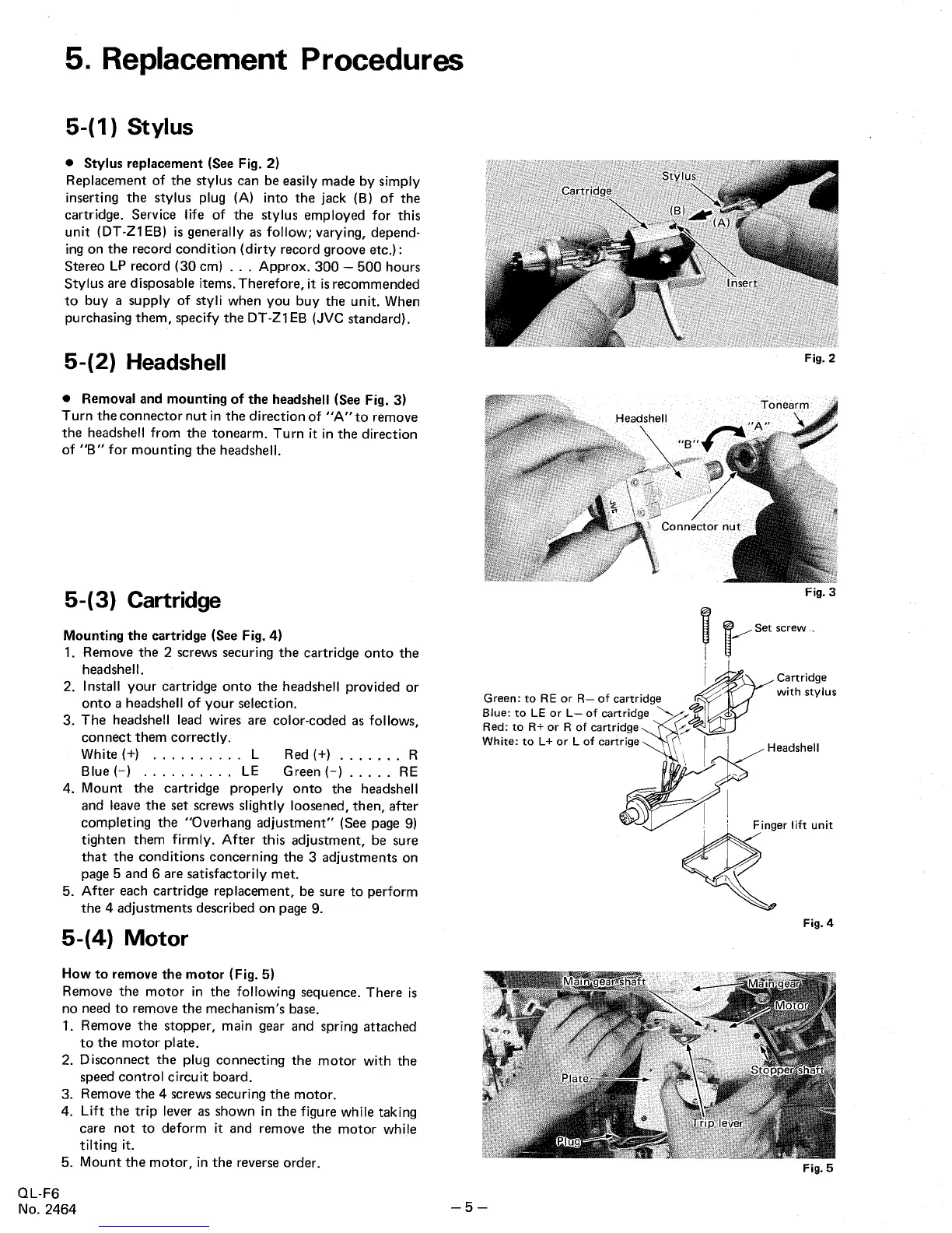
How to remove the motor (Fig. 5)
Remove the motor in
the following sequence. There is
no need to remove the mechanism
s base.
1. Remove the stopper, main gear and spring
attached
to the motor plate.
2. Disconnect the plug connecting the motor with the
speed control circuit board.
3. Remove the
4 screws securing the motor.
4. Lift the trip lever as shown in the figure while taking
care not to deform it and remove the motor while
tilting it.
5. Mount the motor, in the reverse order.
QL-
No. 2464
Fig. 2
Fig. 3
, ~s~"'-
Cartridge
with stylus
Green: to RE or R- of cartridge
Blue: to LE or L- of cartridg
" ~
Red: to R+ or R of cartridge
White: to L+ or L of cartrige \
j ~
Headshell
~ #~"
lift "0"
Fig. 4
Fig.
 Loading...