RC-BX30
1-10
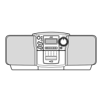
Fig.18
Fig.20
Fig.19
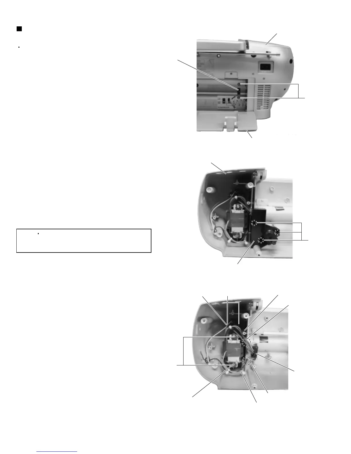
Removing the power transformer
(See Figs.18 to 20.)
1.
2.
3.
4.
5.
6.
7.
From the rear side of the rear cabinet assembly,
remove the battery door. (See Fig.18.)
Remove the two screws P retaining the voltage
selector switch. (See Fig.18.)
From the inside of the rear cabinet assembly,
remove the three screws Q retaining the cassette
deck bracket. (See Fig.19.)
Remove the solders from the soldered section r
and s connecting the wires(red and black).
(See Fig.19.)
Remove the two screws R retaining the power
transformer. (See Fig.20.)
Remove the two screws S retaining the socket
cover. (See Fig.20.)
Take out the power transformer together the socket
cover and voltage selector switch.
Prior to performing the following procedures,
remove the main board and cassette deck/CD
mechanism assembly.
[Note]
When attaching the screws P and R,
apply a locking agent to the screws P
and R.
S
Rear cabinet assembly
Rear cabinet assembly
Battery door
Cassette deck bracket
Power transformer
Soldered
section r
Socket cover
Soldered section s
Voltage
selector
switch
Wire (black)
Wire (red)
Voltage selector
switch
P
P
R

 Loading...