RC-BX30
1-8
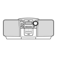
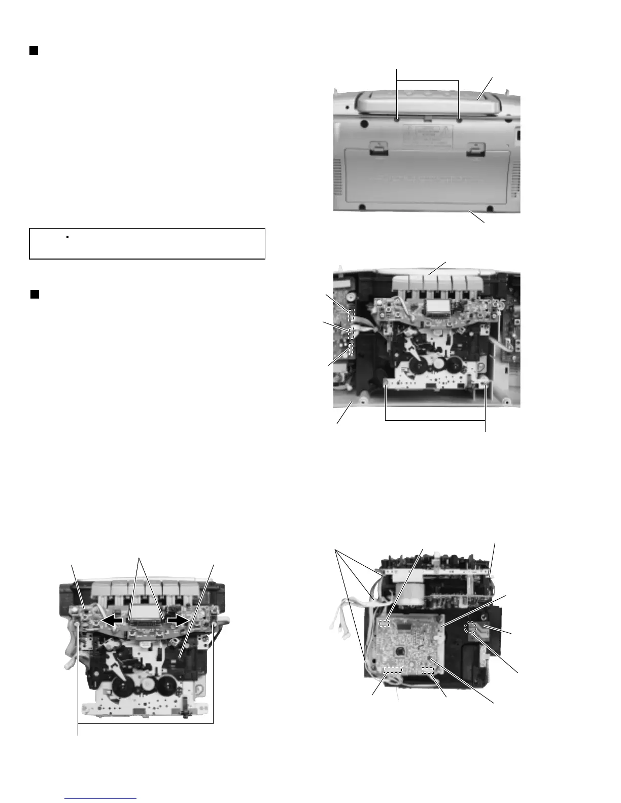
Fig.12
Fig.13
Fig.14Fig.15
Removing the cassette deck/CD
mechanism assembly
(See Figs.12 and 13.)
1.
2.
3.
From the rear side of the rear cabinet assembly,
remove the two screws J retaining the cassette
deck/CD mechanism assembly. (See Fig.12.)
Disconnect the wires from the connectors CN302,
CN303 and CN501 on the main board.
(See Fig.13.)
Remove the two screws K retaining the cassette
deck/CD mechanism assembly. (See Fig.13.)
[Note]
When attaching the screws K, apply a
locking agent to the screws K.
Removing the display board
(See Figs.14 and 15.)
1.
2.
3.
4.
5.
From the bottom side of the CD mechanism
assembly, remove the tie bands bundling the wires
from the CD mechanism assembly. (See Fig.14.)
Disconnect the wires from the connectors BC01,
BC02 and BC03 on the CD servo board.
(See Fig.14.)
Remove the solders from the soldered section j
connecting the wires to the micro switch board.
(See Fig.14.)
Remove the two screws L retaining the display
board. (See Fig.15.)
Press the claws k in the direction of the arrow,
remove the display board. (See Fig.15.)
J
Cassette deck/CD
mechanism assembly
Rear cabinet assembly
Rear cabinet assembly
BC01
BC02
BC03Tie bands
CD mechanism
assembly
Cassette desk
mechanism assembly
Tie band
Display board
Claws k
CD servo board
Soldered
section j
Micro switch
board
CN302
CN303
CN501
Cassette deck/CD mechanism assembly
K
L
 Loading...