RC-BX30
1-20
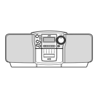
AN7312 (IC201) : Dual recording/Playback pre-amplifier circuit with ALC
1. Terminal layout
3. Pin function
2. Block diagram
1
2
3
4
5
6
7
8
9
10
11
12
13
14
GND
ALC time constant
ALC input Ch.1
Output Ch.1
Phase compensation Ch.1
N.E.B. Ch.1
Input Ch.1
Input Ch.2
N.E.B. Ch.2
Phase compensation Ch.2
Output Ch.2
ALC input Ch.2
Ripple filter
Vcc
GND
ALC time constant by resistance and capacitor
Right channel ALC input
Right channel output
Not connect
Right channel negative feed back input
Right channel signal input
Left channel signal input
Left channel negative feed back input
Not connect
Left channel output
Left channel ALC input
Ripple filter
Power supply
Pin No. Symbol Function
-
-
I
O
-
I
I
I
I
-
O
I
-
-
I/O
14 13 12 11 10
9
1 2 3 4 5 6
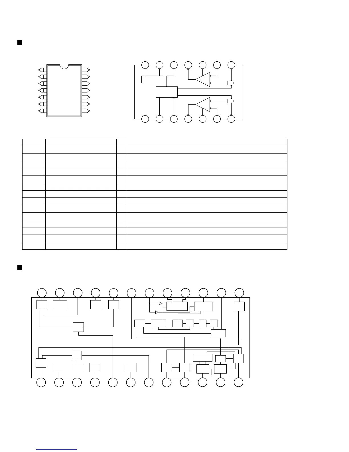
Ripple Filter
Amp.
Ch2
8
ALC
7
GND
Vcc
Amp.
Ch1
FM
RF
FM
MIX
FM
OSC
1
DECODER
PHASE
COMP
DET
CND2
AM
MIX
AM
OSC
AM
RF
REG
GND1
ST
LED
AM-IF
AGCDET
S-METER
TRIG ST-SW VCO FF FF FF
PILOT
Vcc2
2 3 4 5 6 7 8
9 10 11 12
24 23 22 21
20 19 18 17
16 15 14 13
FM-IF
TUN
LED
Vcc1
LA1824 (IC101) : Tuner
1. Terminal layout & Block diagram
Description of major ICs
1
2
3
4
5
6
7
14
13
12
11
10
9
8

 Loading...