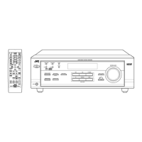
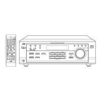
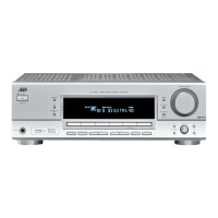
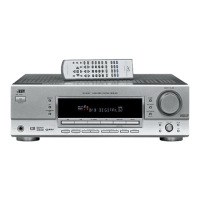
RX-5020VBK/RX5022VSL
1-8
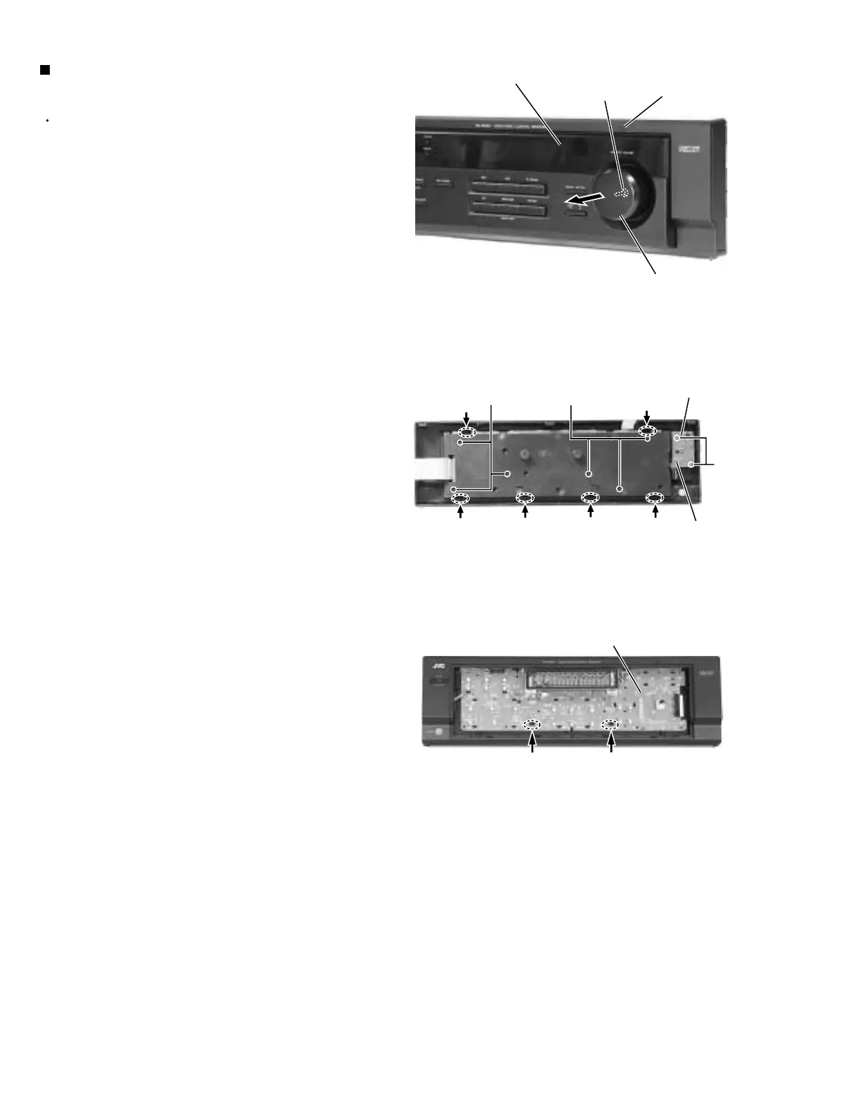
Prior to performing the following procedure, remove
the top cover and the front panel assembly.
Pull out the volume knob on the front side of the front
panel and remove the nut attaching the system
control board.
Remove the two screws Q attaching the power
switch board.
Disconnect the harness from connector CN714 on
the power switch board.
Remove the six screws R attaching the system
control board on the back of the front panel.
On the back of the front panel, release the six joints
by pushing the joint tabs inward.
Remove the operation switch panel toward the front.
Release the two hook attaching the system control
board.
1.
2.
3.
4.
5.
6.
Removing the system control board /
power switch board (See Fig.16 to 18)
Fig.16
Fig.17
Fig.18
Front panel assembly
Nut
Volume knob
System control board
Power switch
board
R
R
CN714
Q
Joint
Joint
Joint
Joint
Joint
Joint
Hook
Hook
Operation switch panel
 Loading...