1-14 (No.MB003)
SECTION 5
TROUBLE SHOOTING
5.1 Self-diagnose function
This model incorporates the following self-diagnostic functions.
1. PROTECTOR
• The PROTECTOR IN port detects errors such as speaker overcurrent and DC voltage output errors (Active: L). Immediately after
detection, all relays are switched off and the alarm display as shown below (blinking at intervals of 0.5 sec. ON and 0.5 sec. OFF)
is displayed in the lower part of the FL matrix.
During the alarm display, all other FL and LED segments are turned off.
OVERLOAD
• The overload status can be canceled by switching the power off. When the power is switched on again, the unit is turned on in
the same abnormal status as before. Lower the volume level for 10 steps for protection. (If the previous volume level was be-
tween 0 and 9, lower it to 0).
• The detection by the protector is not performed for 4 seconds after power on.
2. Supply voltage error detection
• When the power is switched on, the supply voltage at the A/D input port (pins 2 to 5 and 7) is monitored and, when an error is
detected continuously for 1 second, the unit immediately enters the standby mode.
• When the power is switched on again, the unit is turned on in the same abnormal status as before.
• The supply voltage error detection is not performed for 4 seconds after power on.
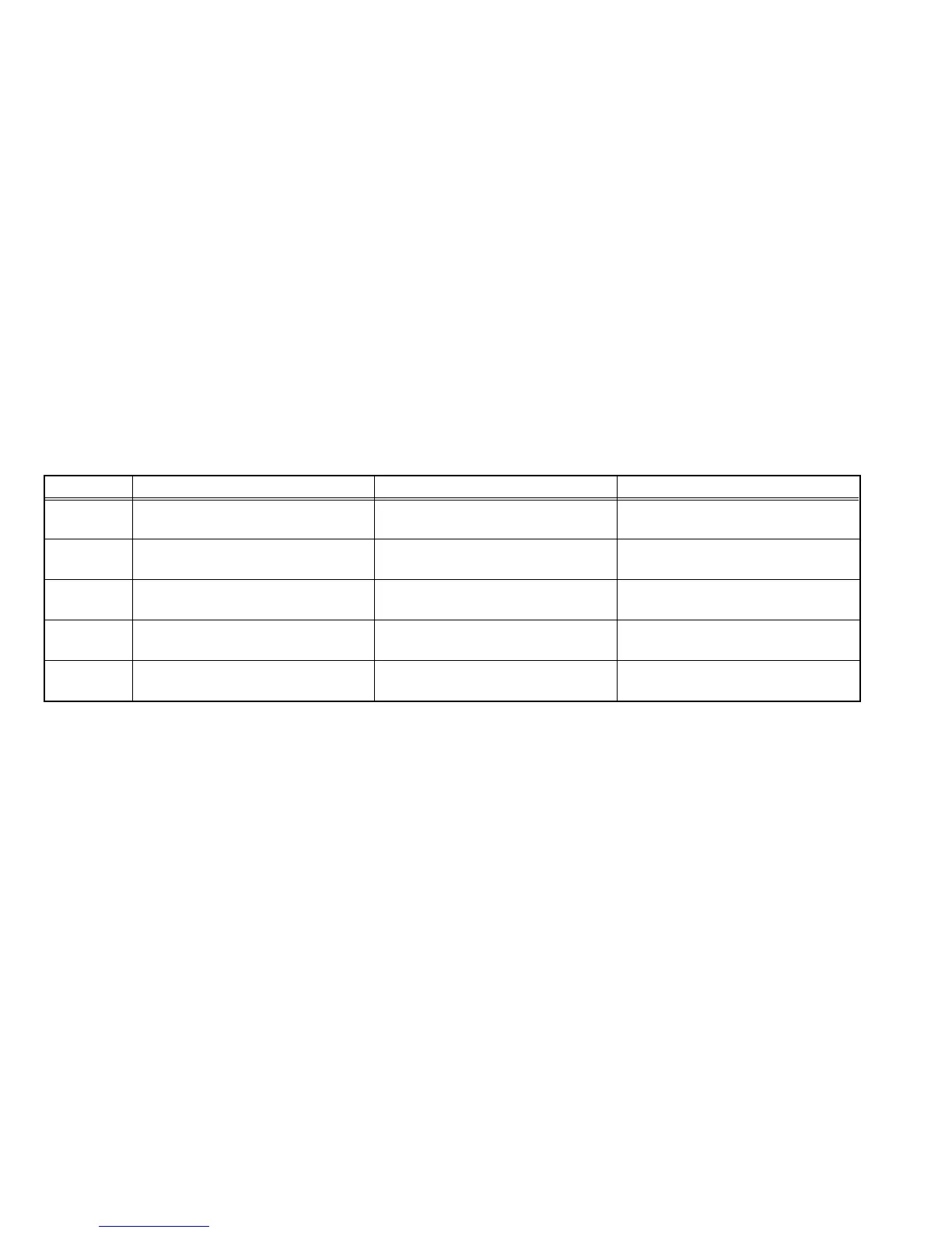
• The following table shows the error detection thresholds.
At abnormal state (Low voltage) At normal state At abnormal state (High voltage)
Pin 2
Analog value : 0 - 2.2
Digital value : 000 - 1C0
Analog value : 2.2 - 2.8
Digital value : 1C1 - 240
Analog value : 2.8 - 5.0
Digital value : 241 - 3FF
Pin 3
Analog value : 0 - 2.2
Digital value : 000 - 1C0
Analog value : 2.2 - 2.8
Digital value : 1C1 - 240
Analog value : 2.8 - 5.0
Digital value : 241 - 3FF
Pin 4
Analog value : 0 - 2.2
Digital value : 000 - 1C0
Analog value : 2.2 - 2.8
Digital value : 1C1 - 240
Analog value : 2.8 - 5.0
Digital value : 241 - 3FF
Pin 5
Analog value : 0 - 2.2
Digital value : 000 - 1C0
Analog value : 2.2 - 2.8
Digital value : 1C1 - 240
Analog value : 2.8 - 5.0
Digital value : 241 - 3FF
Pin 7
Analog value : 0 - 2.2
Digital value : 000 - 1C0
Analog value : 2.2 - 2.8
Digital value : 1C1 - 240
Analog value : 2.8 - 5.0
Digital value : 241 - 3FF
 Loading...