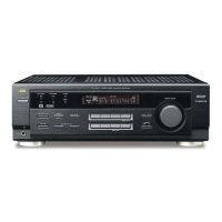
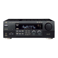
1-8 (No.MB003)
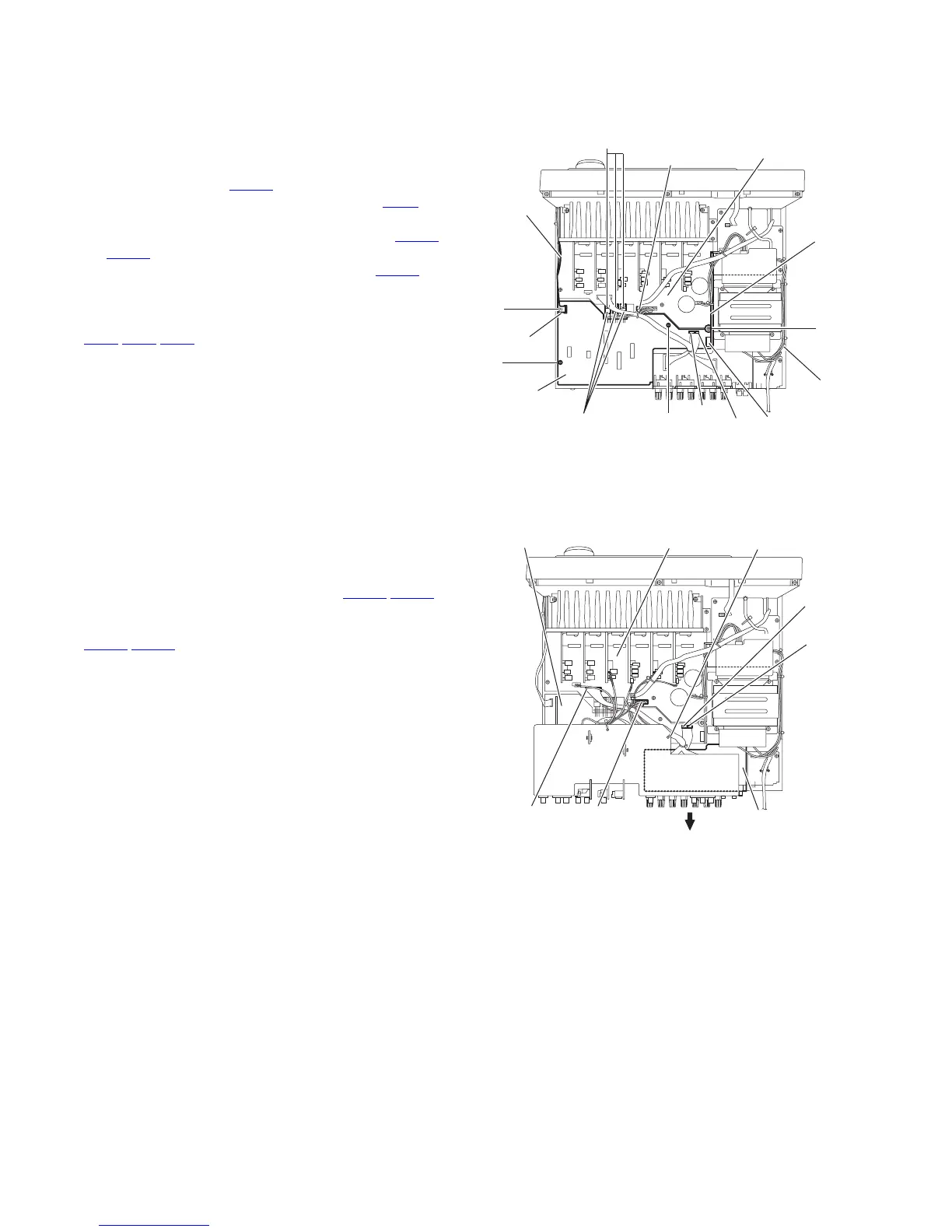
3.6 Removing the micon board
(See Fig.7)
• Prior to performing the following procedures, remove the top
cover, rear panel, I/O board, tuner, DSP board, audio board,
video board and S-video board.
(1) From the top side of the main body, disconnect the card
wire from the connector CN400
on the micon board.
(2) Disconnect the relay board from the connectors CN81
on
the micon board.
(3) Disconnect the parallel wire from the connectors CN931
and CN932 on the micon board.
(4) Disconnect the parallel wire from the connector CN831 on
the main board.
(5) Remove the three screws H attaching the micon board.
(6) Remove the three screws J attaching the transistors
(Q921
,Q931,Q941) to the chassis base.
(7) Loosen the screw K attaching the micon board.
Fig.7
3.7 Removing the speaker board
(See Fig.8)
• Prior to performing the following procedures, remove the top
cover and rear panel.
(1) From the top side of the main body, remove the tie band
bundling the wires.
(2) Disconnect the wires from the connectors (CN813
,CN814)
on the main board.
(3) Disconnect the parallel wire from the connectors
(CN931
,CN932) on the micon board.
(4) Take out the speaker board in the direction of the arrow.
Fig.8
CN400
Micon board
Relay
board
CN81
Card wire
CN931
CN932
H
H
H
J
Transistors
(Q921,Q931,Q941)
Chassis
base
K
CN831
Main board
Tie band
CN813
Main board
Speaker board
CN814
CN931
CN932
Micon board
 Loading...