3
English
Get t ing St ar t ed
This section explains how to connect audio/ video components and speakers to the receiver, and how to connect the
power supply.
ANTENNA
AM
EXT
AM
LOOP
FM 75
COAXIAL
AM
LOOP
ANTENNA
AM
EXT
FM 75
COAXIAL
AM
LOOP
ANTENNA
AM
EXT
FM 75
COAXIAL
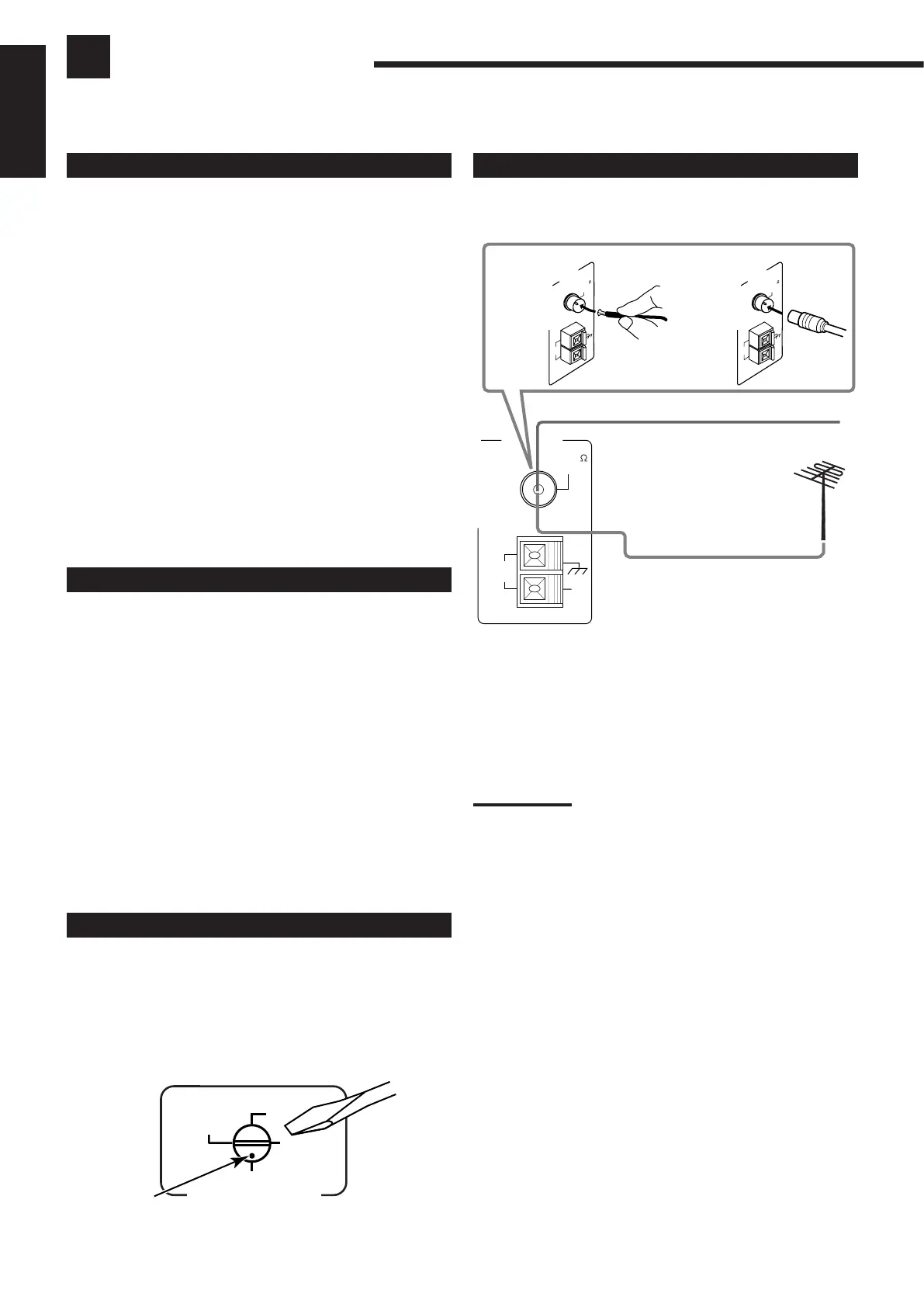
A. Using the Supplied FM Antenna
The FM antenna provided can be connected to the FM 75 Ω
COAXIAL terminal as temporary measure.
B. Using the Standard Type Connector (Not Supplied)
A standard type connector should be connected to the FM 75 Ω
COAXIAL terminal.
Note:
If reception is poor, connect the outdoor antenna.
Before attaching a 75
Ω
coaxial cable (the kind with a round wire
going to an outdoor antenna), disconnect the supplied FM antenna.
B
FM Antenna
Outdoor FM Antenna Cable
Extend the supplied FM antenna horizontally.
A
Connect ing t he FM and AM Ant ennas
FM Ant enna Connect ions
Before Inst allat ion
Gener al
• Be sure your hands are dry.
• Turn the power off to all components.
• Read the manuals supplied with the components you are going to
connect.
Locat ions
• Install the receiver in a location that is level and protected from
moisture.
• The temperature around the receiver must be between –5˚ C and
35˚ C (23˚ F and 95˚ F).
• Make sure there is good ventilation around the receiver. Poor
ventilation could cause overheating and damage the receiver.
Handling t he r eceiver
• Do not insert any metal object into the receiver.
• Do not disassemble the receiver or remove screws, covers, or
cabinet.
• Do not expose the receiver to rain or moisture.
Checking t he Supplied Accessories
Check to be sure you have all of the following items, which are
supplied with the receiver.
The number in the parentheses indicates quantity of the pieces
supplied.
• Remote Control (1)
• Batteries (2)
• AM Loop Antenna (1)
• FM Antenna (1)
• AC Plug Adaptor (1)
If anything is missing, contact your dealer immediately.
Set t ing t he Volt age Select or Swit ch
Before connections, always do the following first if necessary.
Set the correct voltage for your area with the voltage selector switch
on the rear panel. Rotate the voltage selector using a screw driver, so
the voltage number the voltage mark is set at is the same as the
voltage where you are plugging in the receiver.
VOLTAGE SELECTOR
220V
230
-
240V
127V
110V
Voltage mark