(No.MB303)1-9
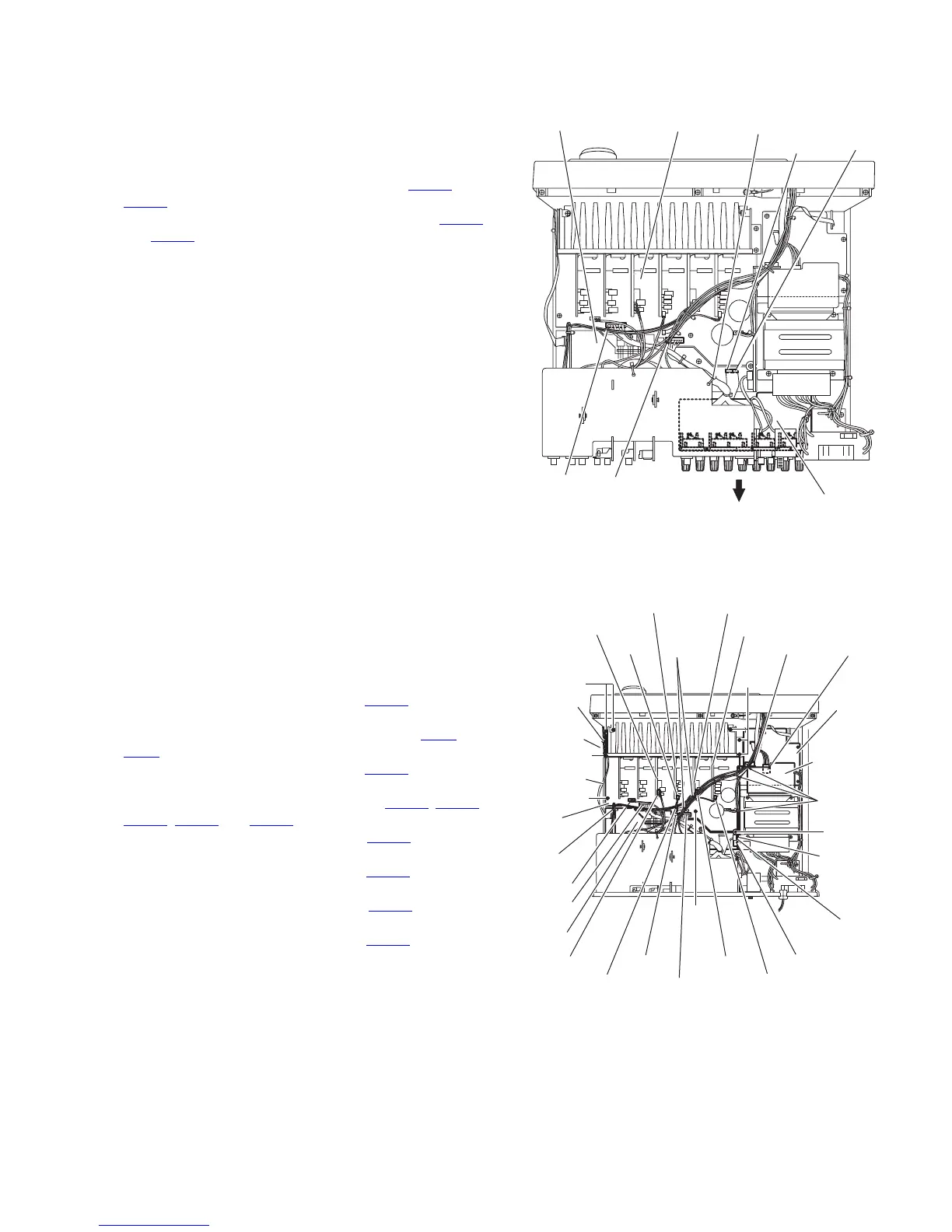
3.8 Removing the speaker board
(See Fig.9)
• Prior to performing the following procedures, remove the top
cover, rear panel.
(1) From the top side of the main body, remove the tie band
bundling the wires.
(2) Disconnect the wires from the connectors (CN813
and
CN814
) on the main board.
(3) Disconnect the parallel wire from the connectors (CN931
and CN932) on the micon board.
(4) Take out the speaker board in the direction of the arrow.
Fig.9
3.9 Removing the relay board and main board
(See Fig.10)
• Prior to performing the following procedures, remove the top
cover.
(1) From the top side of the main body, remove the tie bands
bundling the card wire and wires.
(2) Remove the tie band and wire protection board bundling
the card wire.
(3) Disconnect the wire from the connector CN811
on the pow-
er transformer board 1.
(4) Disconnect the relay board from the connectors (CN71 and
CN81
) on the power supply board and micon board.
(5) Disconnect the wire from the connector CN262 on the relay
board, and take out this board.
(6) Disconnect the wires from the connectors (CN723
, CN813,
CN814, CN831 and CN881) on the main board.
(7) Disconnect the wire from the connector CN722
on the cen-
ter board.
(8) Disconnect the wire from the connector CN714
on the front
board (L).
(9) Disconnect the wire from the connector CN717
on the sur-
round back board.
(10) Disconnect the wire from the connector CN719
on the front
board (R).
(11) Remove the screw M, six screws N and two screws P at-
taching the main board.
(12) Take out the main board.
Fig.10
Tie band
CN813
Main board
Speaker board
CN814
CN931 CN932
Micon board
Tie band
Wire
protection
board
Micon
board
Card wire
Tie bands
CN811
Power
transforme
board 1
CN71
CN81
Relay
board
Power
supply
board
CN831
CN881
Main
board
Tie
band
CN723
CN814
CN813
Center board
CN722
Front board(L)
CN714
Surround back board
CN717
Front board(R)
CN719
M
P
P
N
N
N
Tie band
CN262
 Loading...