(No.MB364)1-13
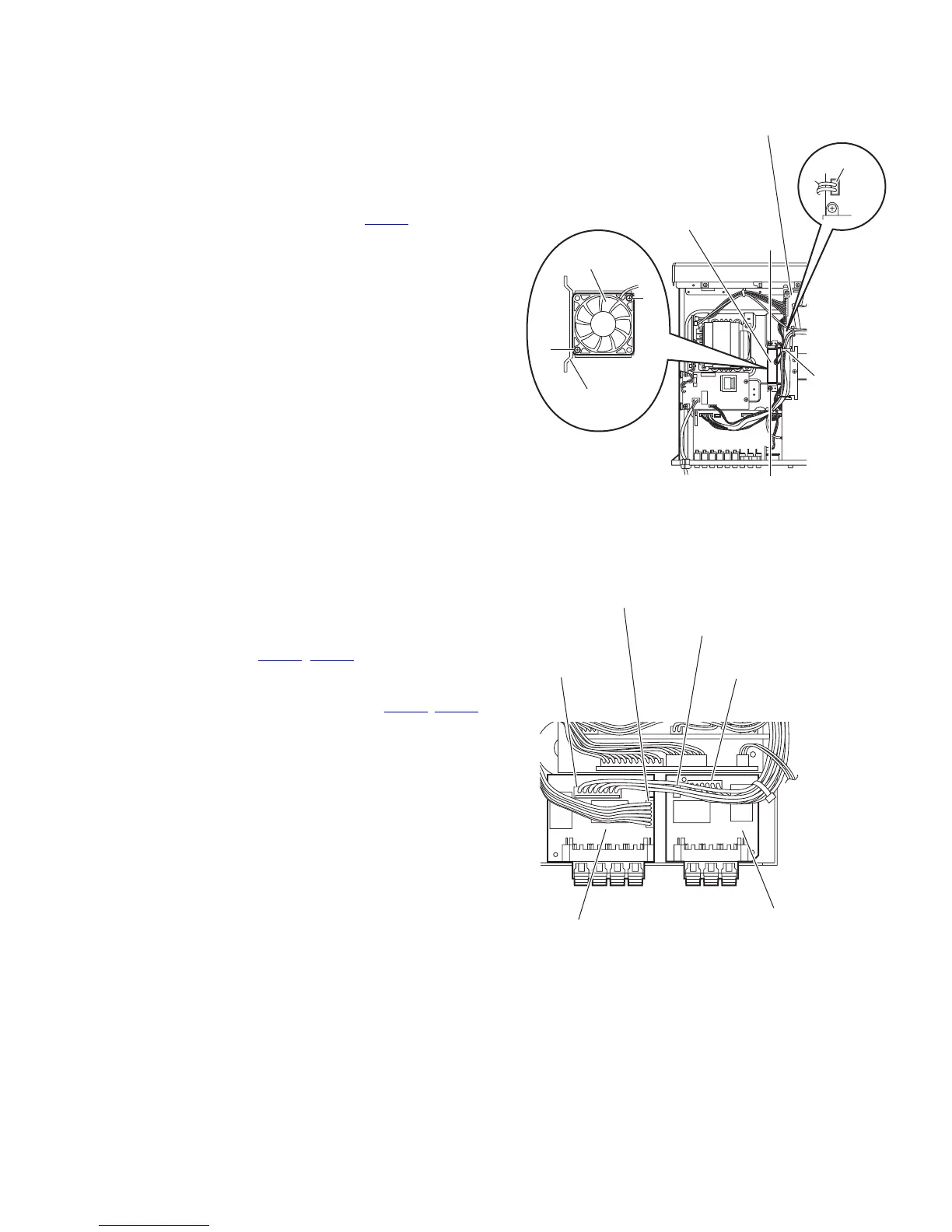
3.1.15 Removing the fan motor
(See Fig.12.)
• Remove the top cover.
(1) From the top side of the main body, remove the tie band
bundling the wires.
Reference:
After reassembling, bundle the wires with a new tie band
as before.
(2) Disconnect the wire from the connector CN103
on the main
amplifier board.
(3) Remove the two screws R and take out the fan motor as-
sembly.
(4) Remove the two screws S attaching the fan motor to the
fan bracket.
Fig.12
3.1.16 Removing the speaker terminal 1 and speaker terminal 2 boards
(See Fig.13)
• Remove the top cover and rear panel.
Reference:
Remove the tuner and subwoofer board as required.
(1) From the top side of the main body, disconnect the wires
from the connectors (CN261
, CN461) on the speaker ter-
minal 1 board.
(2) Take out the speaker terminal 1 board from the main body.
(3) Disconnect the wires from the connectors (CN209
, CN262)
on the speaker terminal 2 board.
(4) Take out the speaker terminal 2 board from the main body.
Fig.13
R
Fan motor assembly
R
CN103
Main amplifier board
Tie band
S
Fan motor
S
Fan bracket
CN261
CN262
CN461
CN209
Speaker terminal 2 board
Speaker terminal 1 board

 Loading...


