1-14 (No.MB364)
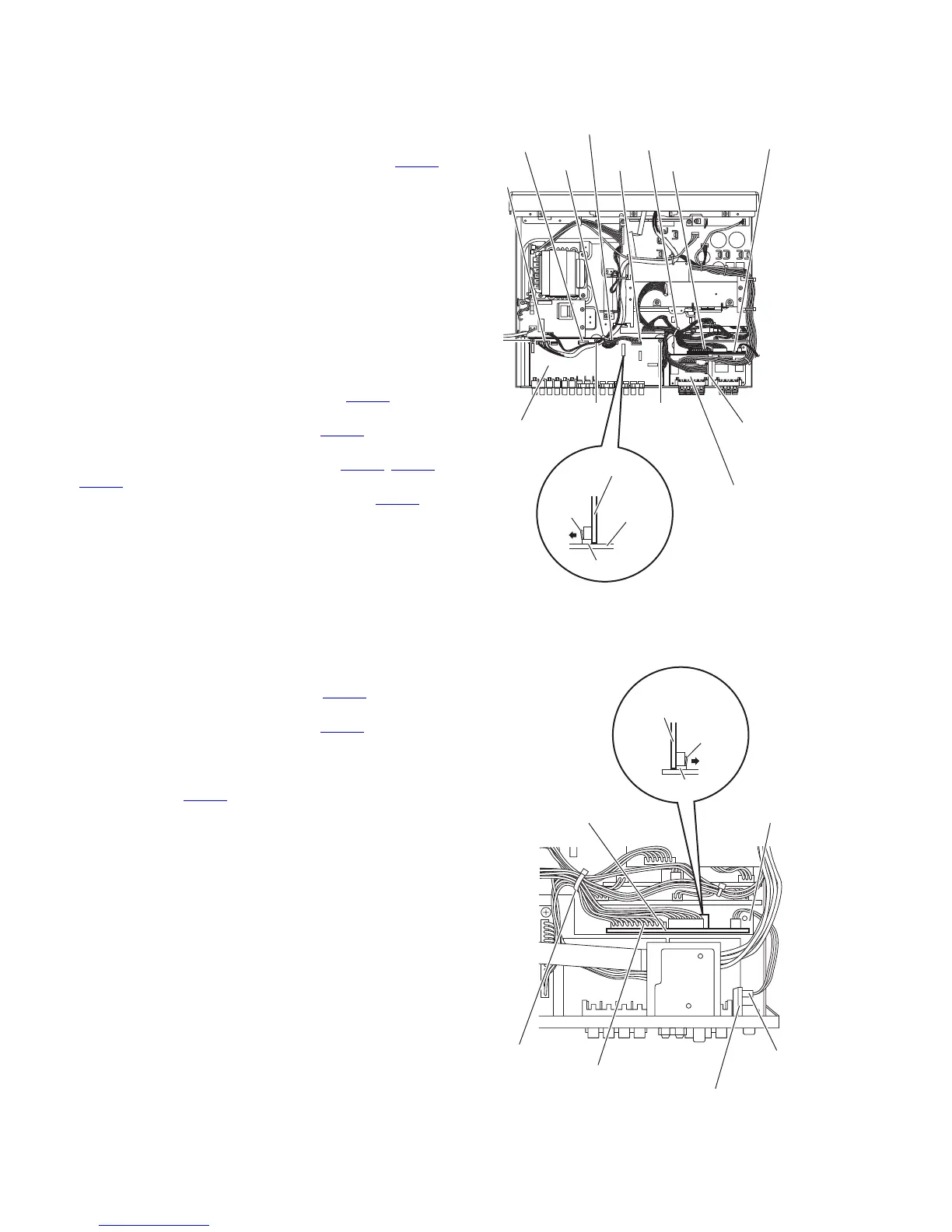
3.1.17 Removing the DSP connect board
(See Fig.14)
• Remove the top cover, rear panel, tuner, compulink board and
DSP board.
Disconnect the DSP connect board from the input board in an up-
ward direction while releasing the claw k of the connector CN502
on the input board.
Note:
When releasing the claw k, take care not to break it.
3.1.18 Removing the input board
(See Fig.14)
• Remove the top cover, rear panel, tuner, compulink board,
DSP board and DSP connect board.
(1) Remove the tie bands bundling the wires.
Reference:
After reassembling, bundle the wires with the new tie
bands as before.
(2) Disconnect the wire from the connector CN209
on the
speaker terminal 2 board.
(3) Disconnect the wire from the connector CN513
on the OSD
connect 1 board.
(4) Disconnect the wires from the connectors (CN530
, CN531,
CN552) on the input board.
(5) Disconnect the parallel wire from the connector CN540 on
the input board.
(6) Remove the three screws T and take out the input board
from the main body.
Fig.14
3.1.19 Removing the OSD connect 1 board
(See Fig.15)
• Remove the top cover and DSP board.
(1) Remove the tie band bundling the wires.
(2) Disconnect the wire from the connector CN524
on the sub-
woofer board.
(3) Disconnect the wire from the connector CN513
on the OSD
connect 1 board.
(4) Disconnect the OSD connect 1 board from the main ampli-
fier board in an upward direction while releasing the claw m
of the connector CN222
on the main amplifier board.
Note:
When releasing the claw m, take care not to break it.
Fig.15
T
CN552
CN540
CN530
CN531
T
Tie band
Input board
T
Tie band
Speaker terminal 2 board
CN209
CN513
OSD connect 1 board
CN502
k
DSP connect
board
Input board
CN222
m
OSC connect 1
board
CN513
Tie band
OSC connect 1 board
Main amplifier board
Subwoofer board
CN524

 Loading...


