(No.MB364)1-15
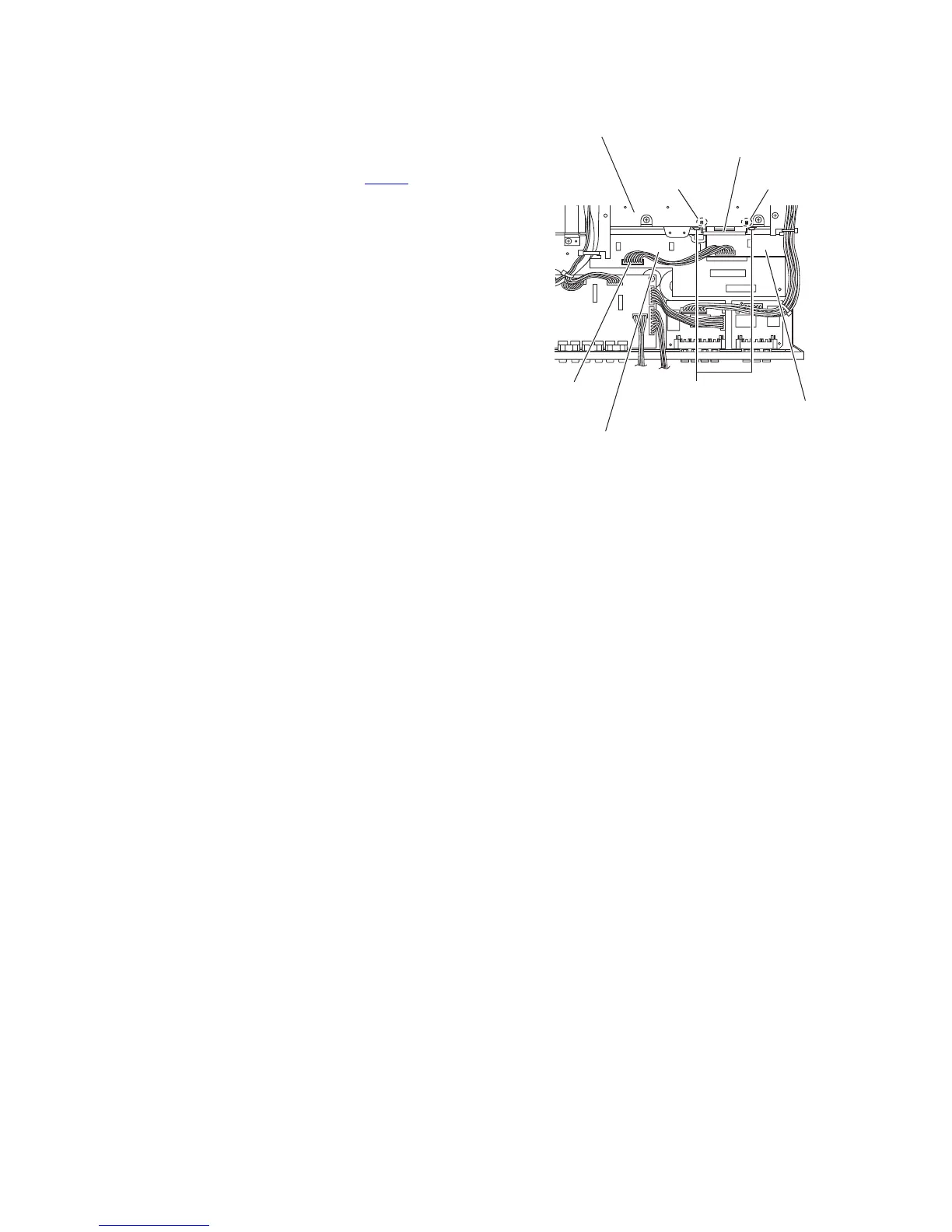
3.1.20 Removing the master clock board
(See Fig.16)
• Remove the top cover, tuner, DSP board, PWM modulation 1
board, PWM modulation 2 board and OSD connect 1 board.
(1) Remove the two screws U with a short driver and remove
the transistor hold from the joints n of the heat sink.
(2) Disconnect the wire from the connector CN201
on the main
amplifier board.
(3) Take out the master clock board from the main body.
Fig.16
U
n
n
Heat sink
Transistor hold
Master clock board
Main amplifier board
CN201

 Loading...


