RX-DV3SL
1-5
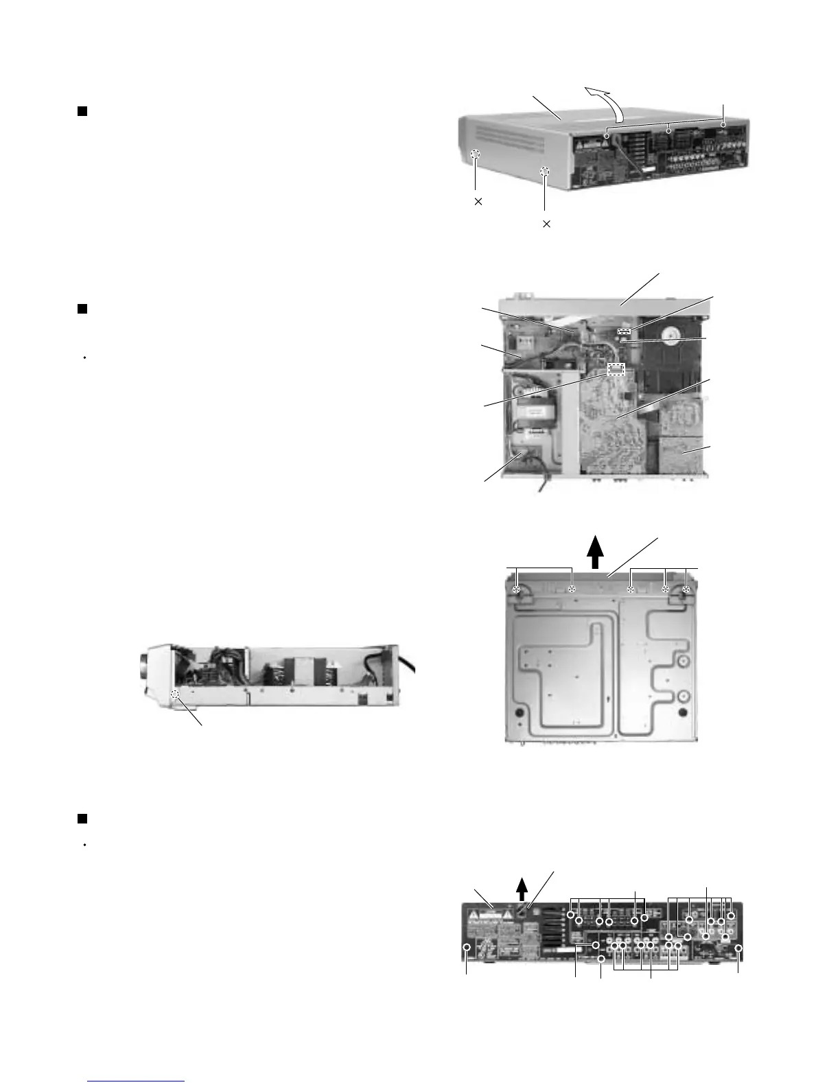
Remove the four screws marked A attaching the top
cover on both sides of the body.
Remove the three screws marked B on the back of
the body.
Remove the top cover from behind in the direction of
1.
2.
3.
Disassembly method
Removing the top cover (See Fig.1)
Prior to performing the following procedures, remove
the top cover.
Remove the power cord stopper from the rear panel
by moving it in the direction of the arrow.
Remove the twenty one screws marked D attaching
each boards to the rear panel on the back of the
body.
Remove the three screws marked E attaching the
rear panel on the back of the body.
1.
2.
3.
Removing the rear panel (See Fig.5)
Prior to performing the following procedures, remove
the top cover.
Disconnect the card wire from the connector CN114
on the main board.
Remove the five screws marked C attaching the front
panel assembly on the bottom of the body. Detach
the front panel assembly toward the front.
Release the two joints marked a on both sides on the
bottom of the body using a screwdriver.
1.
2.
3.
Removing the front panel assembly
(See Fig.2 to 4)
Fig.1
Fig.2
Fig.3
Fig.4
A
2
A 2
B
Top cover
C
Power
supply
board
DSP
board
Main
board
Tie band
D
E
Cord stopper
C
Front panel assembly
Front panel assembly
D
Rear panel
CN114
E
E
Amplifier
board
Power
/Fuse
board
CN201
Joint a
Fig.5
D
D
 Loading...


